Content for TS 23.228 Word version: 18.6.0
1…
3…
4…
4.2.4…
4.3…
4.4…
4.13…
4.16…
5…
5.2…
5.3…
5.4…
5.4.7…
5.4.8…
5.4a…
5.5…
5.5.3…
5.6…
5.6.3…
5.7…
5.7.3…
5.7.5…
5.7.8…
5.8…
5.10…
5.11…
5.11.3…
5.11.3.3
5.11.3.4
5.11.4…
5.11.5…
5.11.5.3…
5.11.6…
5.12…
5.16…
5.16.2…
5.19…
5.20…
A…
E…
E.2.2…
G…
G.5…
H
I…
J…
K…
L…
M…
M.3…
N…
P…
Q…
Q.2.5…
R…
S…
T…
U…
U.2…
V…
W…
X…
Y…
Z…
AA…
AA.3…
AB…
AC…
AC.7…
AC.7.2…
AC.7.2.2
AC.7.2.3…
AC.7.4…
AC.9…
Y IP-Connectivity Access Network specific concepts when using 5GS to access IMS
Y.0 General
Y.1 Mobility related concepts
Y.1.0 General
Y.1.1 Procedures for P-CSCF discovery
Y.2 QoS related concepts
Y.2.1 Application Level Signalling for IMS
Y.2.2 The QoS requirements for an IMS session
Y.2.3 Interaction between 5GS QoS and session signalling
Y.2.4 Network initiated session release - P-CSCF initiated
Y.3 Address and identity management concepts
Y.3.1 Deriving IMS identifiers from the USIM
Y.4 IP version interworking in IMS
Y.5 Usage of NAT in 5GS
Y.6 Retrieval of Network Provided Location Information in 5GS
Y.7 Geographical Identifier
Y.8 Support for Paging policy differentiation for IMS services
Y.9 Support of IMS Services for roaming users
Y.9.1 General
Y.9.2 Architecture without IMS-level roaming interfaces
Y.9.3 Architecture with IMS-level roaming interfaces
Y.9.4 Subscription to changes in PLMN ID at IMS Initial Registration
Y.10 Support of RAN Assisted Codec Adaptation
Y.12 P-CSCF Registration in NRF
Y.13 Subscription to EPS Fallback Event
...
...
Y (Normative) IP-Connectivity Access Network specific concepts when using 5GS to access IMS |R15| p. 329
Y.0 General p. 329
This clause describes the main IP-Connectivity Access Network specific concepts that are used for the provisioning of IMS services over 5GS.
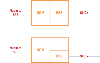
HSS is used to store IMS related subscription and context as shown in the Figure 4.0 "Reference Architecture" specified in clause 4.0. For 5GS, HSS functionality for IMS shall continue to be as standalone regardless if it is co-located or implemented as part of the UDM. When the HSS and UDM are deployed as separate network functions, their interaction is defined by TS 23.632 and TS 29.563, or it may be implementation specific. A single IMS subscription profile is used regardless of UE accessing IMS via different IP-CANs.

From IMS perspective, either the N5 interface as specified in TS 23.503 or the Rx interface as specified in TS 23.203 are used between the P-CSCF and the Policy Control Function (PCF).
In 5G System the Gm reference point defined in clause 4.0 and clause 4.4 is supported for the communication between UE and IMS, e.g. related to registration and session control. Therefore, the same interface is used, i.e. Gm, from P-CSCF perspective towards the UE, when UE is in 5G System or any other IP-CAN.
Y.1 Mobility related concepts p. 329
Y.1.0 General p. 329
To support IMS, the UE shall establish a PDU session with PDU session type set to IP for the corresponding DNN (see clause 5.6.1 of TS 23.501), and acquire an IP address according to clause 5.8.2.2 of TS 23.501. If IMS Multimedia Telephony Service as specified in TS 22.173 is to be used within the PDU session, SSC mode 1 shall be set for the PDU session. In this release of the specification, it is assumed that single PDU session with multiple PDU session anchors defined in clause 5.6.4 of TS 23.501 is not applicable for PDU sessions dedicated to IMS.
If the UE changes its IP address due to changes triggered by the 5GS procedures or due to, for example, PLMN change, then the UE shall re- register in the IMS.
If the UE acquires an additional IP address, then the UE may perform an IMS registration using this additional IP address as the contact address. If IMS registration is performed, this IMS registration may co-exist with the previous IMS registration from this UE and the UE shall be notified that this IMS registration results in multiple simultaneous registrations.
In Dual Connectivity with 5GC case, the UE shall use the access network information based on the primary cell of the Master RAN node that is serving the UE for network location information when the UE interacts with IMS, regardless whether the IMS traffic is routed via the Master RAN node or the Secondary RAN node or both.
Y.1.1 Procedures for P-CSCF discovery p. 330
All the procedures described in clause 5.1.1 apply with the following additions:
-
For the option where P-CSCF discovery is part of the IP-CAN connectivity establishment the following applies:
- P-CSCF discovery shall take place during the PDU session establishment procedure see clause 4.3.2 of TS 23.502.
Y.2 QoS related concepts p. 330
Y.2.1 Application Level Signalling for IMS p. 330
Y.2.1.0 General p. 330
When the UE uses 5GS-access for IMS services, it shall be possible to establish at least one QoS flow identified by a QFI for IMS signalling.
Y.2.1.1 QoS Requirements for Application Level Signalling p. 330
It shall be possible to request prioritised handling over the 5GS system for IMS signalling by applying the appropriate 5QI for the established QoS flow for the IMS signalling, see clause 5.7 of TS 23.501.
Y.2.1.2 Void
Y.2.2 The QoS requirements for an IMS session p. 330
Y.2.2.0 General p. 330
The selection, deployment, initiation, and termination of QoS signalling and resource allocation shall consider:
- The general requirements described in clause 4.2.5.
- The QoS handling is described in TS 23.501, TS 23.502 and TS 23.203 and TS 23.503.
Y.2.2.1 Relation of IMS media components and 5GS QoS flows carrying IMS media p. 331
All associated media flows (such as e.g. RTP / RTCP flows) used by the UE to support a single media component are assumed to be carried within the same 5GS QoS flow.
Y.2.3 Interaction between 5GS QoS and session signalling p. 331
Y.2.3.0 General p. 331
The generic mechanisms for interaction between QoS and session signalling are described in clause 5.4.7. The mechanisms described there and the related procedures througout the present specification are applicable to 5GS-accesses as well with the following clarifications:
- An IP-CAN bearer in this specification shall be interpreted as a 5GS QoS flow.
- An IP-CAN session in this specification shall be interpreted as a 5GS PDU session of type IP.
- The negotiation of the bearer establishment mode does not apply for the 5GS.
- The PCEF corresponds to the combination of SMF and UPF.
Y.2.3.1 Resource Reservation with PCF p. 331
The UE or 5GC can initiate the resource reservation request for the media parameters negotiated over SDP using PDU session modification procedure, see clause 4.3.3 of TS 23.502. However, for IMS. the network shall initiate the establishment, modification and termination of 5GS QoS flows triggered by negotiated SDP.
Y.2.4 Network initiated session release - P-CSCF initiated p. 331
Y.2.4.0 General p. 331
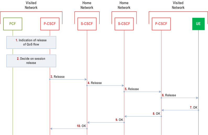
In the event of loss of coverage for 5GS radio access, clause 4.2.6 of TS 23.502, defines the N2 release procedure. This procedure releases the QoS flows. This is indicated to the P-CSCF as shown in Figure Y.3.
Y.2.4.1 Network initiated session release - P-CSCF initiated p. 331
Covers radio coverage loss and that GFBR cannot be maintained by the radio access.

Step 1.
The following steps are only performed in the case the P-CSCF has decided to terminate the session.
In the case of loss of radio coverage or that GFBR cannot be retained in NG-RAN, the 5GC may release the related GBR QoS flow and PCF and P-CSCF are notified appropriately.
Step 2.
The P-CSCF decides on the termination of the IMS session. In the event of the notification that the signalling transport to the UE is no longer possible, the P-CSCF shall terminate any ongoing IMS session with that specific UE. If the P-CSCF decides to terminate the IMS session, it indicates this to PCF, which removes the authorization for resources that had previously been issued for this endpoint for this session. (see TS 23.503).
Step 3.
The P-CSCF generates a Release (Bye message in SIP) to the S-CSCF of the releasing party.
Step 4.
The S-CSCF invokes whatever service logic procedures are appropriate for this ending session. The S-CSCF of the releasing party forwards the Release to the S-CSCF of the other party.
Step 5.
The S-CSCF invokes whatever service logic procedures are appropriate for this ending session. The S-CSCF of the other party forwards the Release on to the P-CSCF.
Step 6.
The P-CSCF of the other party removes the authorization for resources if they have previously been issued for this endpoint for this session. The P-CSCF forwards the Release to the UE.
Step 7.
The UE of the other party responds with a SIP OK to the P-CSCF
Step 8.
Depending on the Bearer Control Mode selected for the IP-CAN session, the release of previously reserved resources shall be initiated either by the UE or by the IP-CAN itself. The SIP OK message is sent to the S-CSCF of the other party.
Step 9.
The S-CSCF of the other party forwards the OK to the S-CSCF of the releasing party.
Step 10.
The S-CSCF of the releasing party forwards the OK to the P-CSCF of the releasing party.
Y.3 Address and identity management concepts p. 332
Y.3.1 Deriving IMS identifiers from the USIM p. 332
If the UICC does not contain an ISIM application, and the permanent user identity is IMSI then clause E.3.1 applies.
Y.4 IP version interworking in IMS p. 333
A PDU session is associated with either an IPv4 or an IPv6 address. For communication with the IMS, the UE shall acquire an IP address according to clause 5.8.2.2.1 of TS 23.501 for the PDU session. The IP address will be either an IPv4 address or and IPv6 address. Hence, a UE will register to the IMS with either an IPv4 or an IPv6 address. Here the P-CSCF and IMS-AGW may support both IP versions and/or may do interworking depending IP version used within the IMS. If the P-CSCF and IMS-AGW do not support both versions, then network design is expected to ensure that IP address incompatibility does not occur.
Y.5 Usage of NAT in 5GS p. 333
There should be no NAT (or its existence should be kept transparent towards the UE) located between the UPF and the P-CSCF, which is possible as they are either located within the same private network and share same address space, or both the UE and the P-CSCF are assigned globally unique IP addresses (see Annex M).
Y.6 Retrieval of Network Provided Location Information in 5GS p. 333
Information related to the location of the user provided by the access network may be required in IMS in order to comply with regulatory requirements (e.g. data retention, lawful interception) and/or in order to enable certain types of added value services based on the user's location.
Depending on usage scenario, the following mechanisms are defined and can be used to retrieve the user location and/or UE Time Zone information from the access network when using 5GS to access IMS:
- The P-CSCF can retrieve the user location and/or UE Time Zone information using PCC mechanisms as specified in TS 23.203 / TS 23.503 and in TS 29.214. Operator policy determines whether to provide the user location and/or UE Time Zone information from the access network in the INVITE request, a MESSAGE request, or within a subsequent message of the dialog.
- When the user location and/or UE Time Zone information is required from the access network but not already available (e.g. when required in an INVITE request, when it is needed prior to session delivery, or when call is broken out to a MGCF), an IMS AS can trigger the retrieval of the user location and/or UE Time Zone information from the AMF via the HSS/UDM as specified in TS 29.328 and as described in clause 4.2.4a.
Y.7 Geographical Identifier p. 333
A network which requires the Geographical Identifier to be generated in the IMS may implement a mapping table between a NG-RAN cell identifier received as part of Access Network Information and a Geographical Identifier. The P-CSCF or an IMS AS may then, based on operator policy, use this mapping table to convert the user location into a Geographical Identifier, and insert the Geographical Identifier in the SIP signalling, thus enabling routing decision in downstream IMS entities or interconnected network.
In the case that a given cell belongs to more than one area identified by a Geographical Identifier, based on operator policy, the P-CSCF or an IMS AS may use the UE mobility analytics provided by NWDAF as specified in TS 23.288.
Y.8 Support for Paging policy differentiation for IMS services p. 334
P-CSCF may support Paging Policy Differentiation (as defined in TS 23.501) for a specific IMS service by marking packet(s) to be send towards the UE related to that IMS service. For such an IMS service, a specific DSCP (IPv4) value and/or a specific Traffic Class (IPv6) value are assigned by local configuration in the P-CSCF.
When Paging Policy Differentiation is deployed in a PLMN, all P-CSCF entities of that PLMN shall homogeneously support it and shall be configured with the same policy for setting the specific DSCP (IPv4) and/or Traffic Class (IPv6) values used by P-CSCF for that feature.
Y.9 Support of IMS Services for roaming users p. 334
Y.9.1 General p. 334
This clause describes support for IMS services for roaming users using IMS level roaming interfaces or without IMS level roaming interfaces.
Y.9.2 Architecture without IMS-level roaming interfaces p. 334
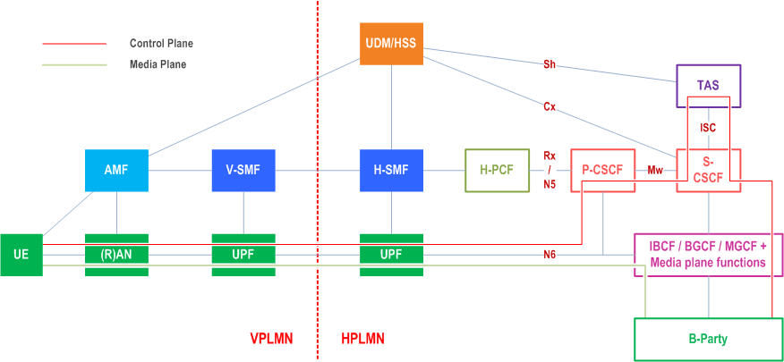
This clause describes the functions that are used to support IMS services for roaming users in deployments without IMS-level roaming interfaces. In this roaming model the UPF holding the UE's IP point of presence is located in the home PLMN and therefore UE IMS signalling and user plane are routed to home PLMN.
The architecture to support IMS services for roaming users, including Voice over IMS in deployments without IMS-level roaming interfaces is shown in Figure Y.9.2-1.
The following architecture requirements apply:
- P-CSCF (in HPLMN) identifies the serving network (VPLMN) where the UE is located using the procedure defined in clause Y.9.3.

Y.9.3 Architecture with IMS-level roaming interfaces p. 335
For IMS services with roaming level interfaces the P-CSCF and UPF are located in VPLMN (local breakout), see clause 4.2.3 and clause M.1. For roaming architecture for voice over IMS with local breakout see clause 4.15a. For information on how to apply the loopback possibility in clause 4.15a, see clause M.3.
Y.9.4 Subscription to changes in PLMN ID at IMS Initial Registration p. 335
In IMS local breakout where P-CSCF is located in VPLMN (see Annex M.1 and Annex M.3), the home network determines the serving PLMN of the UE from the location of the P-CSCF during initial IMS Registration, using the P-CSCF network identifier.
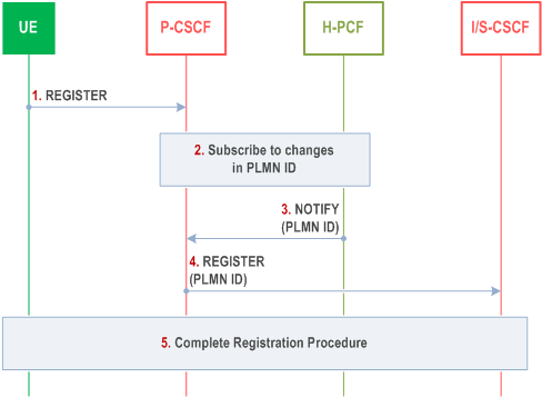
In deployments without IMS-level roaming interfaces, the home network determines the serving PLMN of the UE using procedure defined in TS 23.503, where P-CSCF requests the PCF to report the PLMN identifier where the UE is currently located. The received PLMN ID information is then forwarded in the SIP REGISTER request.
This procedure shall be applied by the P-CSCF at initial UE IMS registration.

Step 1.
The UE sends a SIP REGISTER request to the P-CSCF.
Step 2.
If this is initial IMS registration then the P-CSCF subscribes to the PCF to be notified of the PLMN ID where the UE is currently attached. The subscription to PLMN changes is active as long as the UE is IMS registered.
Step 3.
The PCF forwards the PLMN ID to the P-CSCF. The P-CSCF stores the PLMN ID.
Step 4.
The P-CSCF includes the received PLMN ID in the SIP REGISTER request before forwarding the request to the I-CSCF.
Step 5.
Normal IMS registration procedure is then completed.
Y.10 Support of RAN Assisted Codec Adaptation |R16| p. 336
RAN assisted codec adaptation is supported as described in clause E.10 with the addition that RAN assisted codec adaptation needs to be supported on NR RAT as specified in TS 38.300 and TS 38.321, in addition to E-UTRA RAT.
Y.11 Void
Y.12 P-CSCF Registration in NRF |R16| p. 336
In order to support service based SMF discovery of the P-CSCF using the NRF (as described in clause 5.16.3 of TS 23.501) the P-CSCF's in a network will need to register with an applicable NRF. When a network uses other P-CSCF discovery methods (as described in clause 5.1.1) the P-CSCF does not need to register with the NRF. Local configuration of the P-CSCF is used to determine if the P-CSCF shall perform registration with the NRF.
When the P-CSCF is configured to support SMF discovery of the P-CSCF, P-CSCF shall register in NRF their capabilities using the Nnrf_NFManagement_NFRegister Request message. The NF profile of the P-CSCF registered in NRF shall include the IP address and may include an FQDN if available. The same applies to the Nnrf_NFManagement_NFUpdate Request.
Based on the same configuration, a P-CSCF taken out of service will deregister itself using the Nnrf_NFManagement_NFDeregister Request.
Y.13 Subscription to EPS Fallback Event |R16| p. 337
Based on local configuration in the case of an originating or a terminating session, the P-CSCF may subscribe to the PCF for notification for the EPS Fallback event using existing procedures defined in TS 23.503.
If the PCF reports that an EPS fallback occurred, based on local configuration, the P-CSCF may include this information in outgoing SIP messages towards other IMS nodes.