Content for TS 23.228 Word version: 18.6.0
1…
3…
4…
4.2.4…
4.3…
4.4…
4.13…
4.16…
5…
5.2…
5.3…
5.4…
5.4.7…
5.4.8…
5.4a…
5.5…
5.5.3…
5.6…
5.6.3…
5.7…
5.7.3…
5.7.5…
5.7.8…
5.8…
5.10…
5.11…
5.11.3…
5.11.3.3
5.11.3.4
5.11.4…
5.11.5…
5.11.5.3…
5.11.6…
5.12…
5.16…
5.16.2…
5.19…
5.20…
A…
E…
E.2.2…
G…
G.5…
H
I…
J…
K…
L…
M…
M.3…
N…
P…
Q…
Q.2.5…
R…
S…
T…
U…
U.2…
V…
W…
X…
Y…
Z…
AA…
AA.3…
AB…
AC…
AC.7…
AC.7.2…
AC.7.2.2
AC.7.2.3…
AC.7.4…
AC.9…
5.11.5.3 Session Redirection initiated by S-CSCF to general endpoint (REDIRECT to originating UE#1)
5.11.5.4 Session Redirection initiated by P-CSCF
5.11.5.5 Session Redirection initiated by UE
5.11.5.6 Session Redirection initiated by originating UE#1 after Bearer Establishment (REDIRECT to originating UE#1)
...
...
5.11.5.3 Session Redirection initiated by S-CSCF to general endpoint (REDIRECT to originating UE#1) p. 179
The S-CSCF in the scenario above may determine that the session is to be redirected to an endpoint outside the IP MultiMedia System and outside the CS-domain. Examples of these destinations include web pages, email addresses, etc. It recognizes this situation by the redirected URI being other than a sip: URI or tel: URL.
In cases when the destination subscriber is not currently registered in the IM CN subsystem, the I-CSCF may assign a temporary S-CSCF to invoke the service logic on behalf of the intended destination. This temporary S-CSCF takes the role of S-CSCF#2 in the following information flow. For session redirection to a general endpoint where the S-CSCF of the called party (S-CSCF#2) wishes to use the SIP REDIRECT method, the S-CSCF#2 will pass the new destination information to the originator. As a result the originator should initiate a new session to the redirected-to destination provided by S-CSCF#2. The originator may be a UE as shown in the example flow in Figure 5.38, an Application Server or a non-IMS network SIP client. The originator may also receive a redirect from a non-IMS network SIP client. Only the scenario in which the originating UE receives a redirect based on S-CSCF service logic is shown.
Handling of redirection to a general URI is shown in the following information flow:
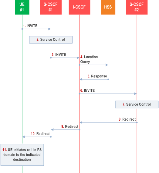
Step-by-step processing is as follows:
Step 1.
The SIP INVITE request is sent from the UE to S-CSCF#1 by the procedures of the originating flow.
Step 2.
S-CSCF#1 invokes whatever service logic is appropriate for this session setup attempt.
Step 3.
S-CSCF#1 performs an analysis of the destination address, and determines the network operator to whom the subscriber belongs. The INVITE message is sent to an I-CSCF for that operator.
Step 4.
I-CSCF queries the HSS for current location information of the destination user.
Step 5.
HSS responds with the address of the current Serving-CSCF (S-CSCF#2) for the terminating user.
Step 6.
I-CSCF forwards the INVITE request to S-CSCF#2, who will handle the session termination.
Step 7.
S-CSCF#2 invokes whatever service logic is appropriate for this session setup attempt. As a result of this service control logic, S-CSCF#2 determines that the session should be redirected to a new destination URI outside the IMS and outside the CS domain, i.e. other than a sip: URI or tel: URL.
Step 8.
S-CSCF#2 sends a SIP Redirect response back to I-CSCF, with redirection destination being the general URI.
Step 9.
I-CSCF sends a Redirect response back to S-CSCF#1, containing the redirection destination.
Step 10.
S-CSCF#1 forwards the Redirect response back to UE#1.
Step 11.
UE#1 initiates the session to the indicated destination.
5.11.5.4 Session Redirection initiated by P-CSCF p. 180
One of the functional elements in a basic session flow that may initiate a redirection is the P-CSCF of the destination user. In handling of an incoming session setup attempt, the P-CSCF normally sends the INVITE request to the destination UE, and retransmits it as necessary until obtaining an acknowledgement indicating reception by the UE.
In cases when the destination user is not currently reachable in the IM CN subsystem (due to such factors as roaming outside the service area or loss of battery, but the registration has not yet expired), the P-CSCF may initiate a redirection of the session. The P-CSCF informs the S-CSCF of this redirection, without specifying the new location; S-CSCF determines the new destination and performs according to clause 5.11.5.1, clause 5.11.5.2, or clause 5.11.5.3 above, based on the type of destination.
This is shown in the following information flow:
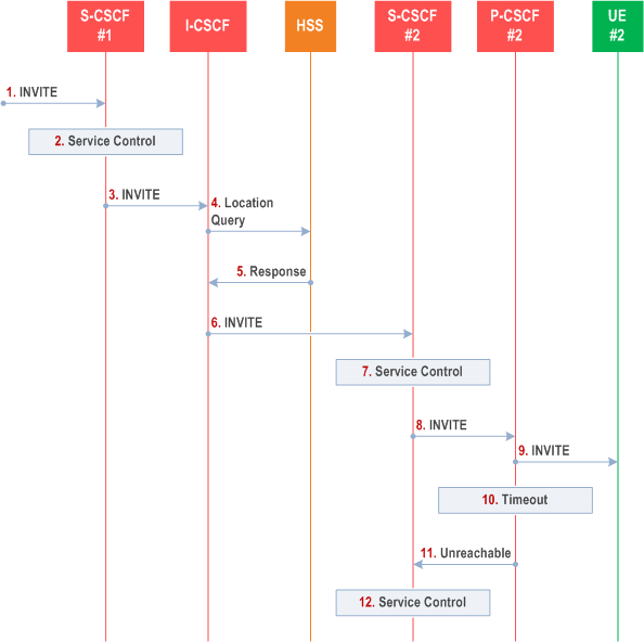
Step-by-step processing is as follows:
Step 1.
The SIP INVITE request is sent from the UE to S-CSCF#1 by the procedures of the originating flow.
Step 2.
S-CSCF#1 invokes whatever service logic is appropriate for this session setup attempt.
Step 3.
S-CSCF#1 performs an analysis of the destination address, and determines the network operator to whom the subscriber belongs. The INVITE message is sent to an I-CSCF for that operator.
Step 4.
I-CSCF queries the HSS for current location information of the destination user.
Step 5.
HSS responds with the address of the current Serving-CSCF (S-CSCF#2) for the terminating user.
Step 6.
I-CSCF forwards the INVITE request to S-CSCF#2, who will handle the session termination.
Step 7.
S-CSCF#2 invokes whatever service logic is appropriate for this session setup attempt.
Step 8.
S-CSCF#2 forwards the INVITE request to P-CSCF#2
Step 9.
P-CSCF#2 forwards the INVITE request to UE#2
Step 10.
Timeout expires in P-CSCF waiting for a response from UE#2. P-CSCF therefore assumes UE#2 is unreachable.
Step 11.
P-CSCF#2 generates an Unavailable response, without including a new destination, and sends the message to S-CSCF#2.
Step 12.
S-CSCF#2 invokes whatever service logic is appropriate for this session redirection. If the user does not subscribe to session redirection service, or did not supply a forwarding destination, S-CSCF#2 may terminate the session setup attempt with a failure response. Otherwise, S-CSCF#2 supplies a new destination URI, which may be a phone number, an email address, a web page, or anything else that can be expressed as a URI. Processing continues according to clause 5.11.5.1, clause 5.11.5.2, or clause 5.11.5.3 above, based on the type of destination URI.
5.11.5.5 Session Redirection initiated by UE p. 181
The next functional element in a basic session flow that may initiate a redirection is the UE of the destination user. The UE may implement customer-specific feature processing, and base its decision to redirect this session on such things as identity of caller, current sessions in progress, other applications currently being accessed, etc. UE sends the SIP Redirect response to its P-CSCF, who forwards back along the signalling path to S-CSCF#1, who initiates a session to the new destination.
The service implemented by this information flow is typically "Session Forward Busy", "Session Forward Variable" or "Selective Session Forwarding".
This is shown in the following information flow:
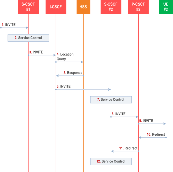
Step-by-step processing is as follows:
Step 1.
The SIP INVITE request is sent from the UE to S-CSCF#1 by the procedures of the originating flow.
Step 2.
S-CSCF#1 invokes whatever service logic is appropriate for this session setup attempt.
Step 3.
S-CSCF#1 performs an analysis of the destination address, and determines the network operator to whom the subscriber belongs. The INVITE message is sent to an I-CSCF for that operator.
Step 4.
I-CSCF queries the HSS for current location information of the destination user.
Step 5.
HSS responds with the address of the current Serving-CSCF (S-CSCF#2) for the terminating user.
Step 6.
I-CSCF forwards the INVITE request to S-CSCF#2, who will handle the session termination.
Step 7.
S-CSCF#2 invokes whatever service logic is appropriate for this session setup attempt.
Step 8.
S-CSCF#2 forwards the INVITE request to P-CSCF#2.
Step 9.
P-CSCF#2 forwards the INVITE request to UE#2.
Step 10.
UE#2 determines that this session should be redirected, and optionally supplies the new destination URI. This new destination URI may be a phone number, an email address, a web page, or anything else that can be expressed as a URI. The Redirect response is sent to P-CSCF#2.
Step 11.
P-CSCF#2 forwards the Redirect response to S-CSCF#2.
Step 12.
S-CSCF#2 invokes whatever service logic is appropriate for this session redirection. If UE#2 does not subscribe to session redirection service, or did not supply a new destination URI, S-CSCF#2 may supply one or may terminate the session setup attempt with a failure response. The new destination URI may be a phone number, an email address, a web page, or anything else that can be expressed as a URI. The procedures of clause 5.11.5.1, clause 5.11.5.2, or clause 5.11.5.3 given above are followed, based on the type of URI.
5.11.5.6 Session Redirection initiated by originating UE#1 after Bearer Establishment (REDIRECT to originating UE#1) p. 182
The UE of the destination user may request the session be redirected after a customer-specified ringing interval. The UE may also implement customer-specific feature processing, and base its decision to redirect this session on such things as identity of caller, current sessions in progress, other applications currently being accessed, etc. UE sends the SIP Redirect response to its P-CSCF, who forwards back along the signalling path to the originating endpoint, who initiates a session to the new destination.
The service implemented by this information flow is typically "Session Forward No Answer".
The originating end point may be a UE as shown in the example flow in Figure 5.41 or it may be any other type of originating entity as defined in clause 5.4a. Redirect to another IMS endpoint (e.g. a sip: URI) is shown in the figure. The redirecting endpoint may be a UE as shown or an Application Server or a non-IMS network SIP client. Further, the endpoint to which the session is redirected may be a UE as shown in Figure 5.41, or it may be any other type of terminating entity as defined in clause 5.4a. Only the scenario in which a call from the first UE is redirected by a second UE to a third UE is shown.
The flow presented here assumes that Policy and Charging Control is in use.
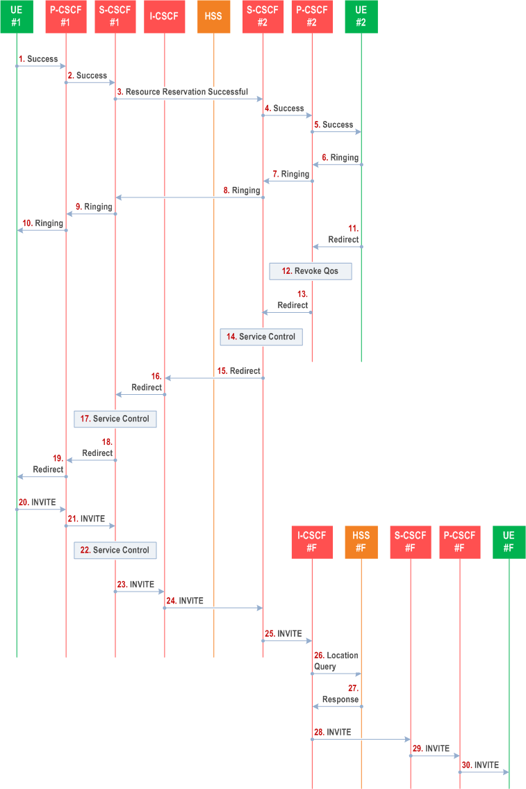
Step-by-step processing is as follows:
Step 1-10.
Normal handling of a basic session establishment, up through establishment of the bearer channel and alerting of the destination user or by a previous session redirection after bearer establishment procedure.
Step 11.
Based on a timeout or other indications, UE#2 decides the current session should be redirected to a new destination URI. This new destination URI may be a phone number, an email address, a web page, or anything else that can be expressed as a URI. The Redirect response is sent to P-CSCF#2.
Step 12.
P-CSCF#2 shall revoke any authorization for QoS for the current session.
Step 13.
P-CSCF#2 forwards the Redirect response to S-CSCF#2.
Step 14.
S-CSCF#2 invokes whatever service logic is appropriate for this session redirection. If UE#2 does not subscribe to session redirection service, or did not supply a new destination URI, S-CSCF#2 service logic may supply one or may terminate the session setup attempt with a failure response. The new destination URI may be a phone number, an email address, a web page, or anything else that can be expressed as a URI. If S-CSCF#2 service logic requires that it remain on the path for the redirected request, the service logic generates a private URI, addressed to itself, as the new destination.
Step 15.
S-CSCF#2 sends a SIP Redirect response back to I-CSCF, containing the new destination URI.
Step 16.
I-CSCF sends a Redirect response back to S-CSCF#1, containing the new destination.
Step 17.
S-CSCF#1 service logic may check the number of redirections that have occurred for this session setup attempt, and if excessive, abort the session. If S-CSCF#1 service logic requires that UE#1 not know the new destination URI, the service logic stores the new destination information, generates a private URI addressed to itself pointing to the stored information, and generates a modified Redirect response with the private URI.
Step 18.
S-CSCF#1 sends the Redirect response to P-CSCF#1.
Step 19.
P-CSCF#1 revokes any authorization for QoS for the current session and sends the Redirect response to UE#1.
Step 20.
UE#1 initiates a new INVITE request to the address provided in the Redirect response. The new INVITE request is sent to P-CSCF#1.
Step 21.
P-CSCF#1 forwards the INVITE request to S-CSCF#1.
Step 22.
S-CSCF#1 invokes whatever service logic is appropriate for this new session setup attempt. The service logic may retrieve destination information if saved in step #17.
Step 23.
S-CSCF#1 determines the network operator of the new destination address. If the service logic in step #14 did not provide its private URI as a new destination, the procedure continues with step #26, bypassing steps #24 and #25. If the service logic in step #14 did provide a private URI as a new destination, the INVITE message is sent to I-CSCF#2, the I-CSCF for S-CSCF#2.
Step 24.
I-CSCF forwards the INVITE to S-CSCF#2.
Step 25.
S-CSCF#2 decodes the private URI, determines the network operator of the new destination, and sends the INVITE request to the I-CSCF for that network operator.
Step 26-30.
The remainder of this session completes as normal.
![]()
![]()
![]()