| |
Figure 4.2.2.2.2-1 | Registration procedure |
Figure 4.2.2.2.3-1 | Registration with AMF re-allocation procedure |
Figure 4.2.2.2.4-1 | UE Registration with ON-SNPN |
Figure 4.2.2.3.2-1 | UE-initiated Deregistration |
Figure 4.2.2.3.3-1 | Network-initiated Deregistration |
Figure 4.2.3.2-1 | UE Triggered Service Request procedure |
Figure 4.2.3.3-1 | Network Triggered Service Request |
Figure 4.2.4.2-1 | UE Configuration Update procedure for access and mobility management related parameters |
Figure 4.2.4.3-1 | UE Configuration Update procedure for transparent UE Policy delivery |
Figure 4.2.5.2-1 | UE Reachability Notification Request Procedure |
Figure 4.2.5.3-1 | UE Activity Procedure |
Figure 4.2.6-1 | AN Release procedure |
Figure 4.2.8a-1 | UE Capability Match Request |
Figure 4.2.9.2-1 | Network Slice-Specific Authentication and Authorization procedure |
Figure 4.2.9.3-1 | AAA Server initiated Network Slice-Specific Re-authentication and Re-authorization procedure |
Figure 4.2.9.4-1 | AAA Server-initiated Network Slice-Specific Authorization Revocation procedure |
Figure 4.2.11.2-1 | Number of UEs per network slice availability check and update procedure |
Figure 4.2.11.2a-1 | Hierarchical NSACF-based number of UEs per network slice availability check and update procedure |
Figure 4.2.11.3-1 | Early Admission Control (EAC) update procedure |
Figure 4.2.11.4-1 | Number of PDU Sessions per network slice availability check and update procedure |
Figure 4.2.11.4a-1 | Hierarchical NSAC-based number of PDU Sessions per network slice availability check and update procedure |
Figure 4.2.11.5.2.3-1 | HPLMN Delegated NSAC admission for UE number Procedure |
Figure 4.2.11.5.2.4-1 | HPLMN Delegated NSAC admission for PDU Session number procedure |
Figure 4.2.11.6-1 | Update of local maximum number in hierarchical NSAC architecture |
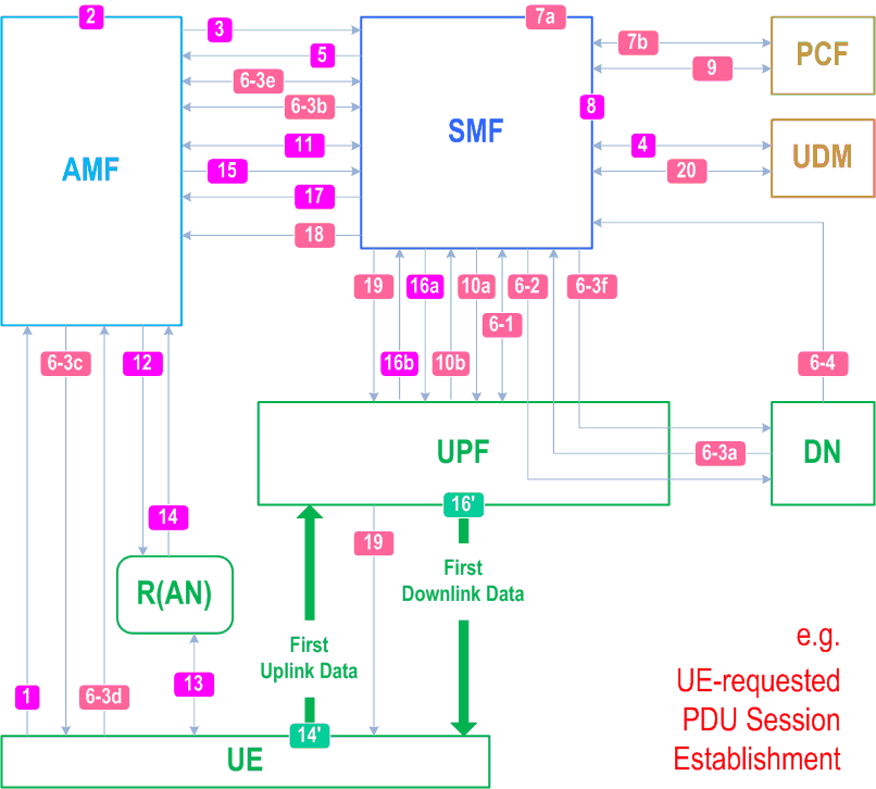
Figure 4.3.2.2.1-1 | UE-requested PDU Session Establishment for non-roaming and roaming with local breakout |
Figure 4.3.2.2.2-1 | UE-requested PDU Session Establishment for home-routed roaming scenarios |
Figure 4.3.2.2.3.2-1 | SMF selection for non-roaming and roaming with local breakout scenarios |
Figure 4.3.2.2.3.3-1 | Option 1 for SMF selection for home-routed roaming scenarios |
Figure 4.3.2.2.3.3-2 | Option 2 for SMF selection for home-routed roaming scenarios |
Figure 4.3.2.3-1 | PDU Session Establishment authentication/authorization by a DN-AAA Server |
Figure 4.3.2.4-1 | Support of L2TP |
Figure 4.3.3.2-1 | UE or network requested PDU Session Modification (for non-roaming and roaming with local breakout) |
Figure 4.3.3.3-1 | UE or network requested PDU Session Modification (for home-routed roaming scenario) |
Figure 4.3.4.2-1 | UE or network requested PDU Session Release for non-roaming and roaming with local breakout |
Figure 4.3.4.3-1 | UE or network requested PDU Session Release for home-routed roaming |
Figure 4.3.5.1-1 | Change of SSC mode 2 PSA for a PDU Session |
Figure 4.3.5.2-1 | Change of SSC mode 3 PDU Session Anchor with multiple PDU Sessions |
Figure 4.3.5.3-1 | Change of PDU Session Anchor with IPv6 Multi homed PDU Session |
Figure 4.3.5.4-1 | Addition of additional PDU Session Anchor and Branching Point or UL CL |
Figure 4.3.5.5-1 | Removal of additional PDU Session Anchor and Branching Point or UL CL |
Figure 4.3.5.6-1 | Change of additional PSA for a PDU Session in IPv6 multi-homing or UL CL case |
Figure 4.3.5.7-1 | Simultaneous change of Branching Point or UL CL and additional PSA for a PDU Session |
Figure 4.3.5.8-1 | Ethernet PDU Session Anchor Relocation |
Figure 4.3.6.2-1 | Processing AF requests to influence traffic routing and/or Service Function Chaining for Sessions not identified by an UE address |
Figure 4.3.6.3-1 | Notification of user plane management event |
Figure 4.3.6.4-1 | Handling an AF request targeting an individual UE address to the relevant PCF |
Figure 4.3.6.5.2-1 | Processing an AF request to influence traffic routing for HR-SBO session when AF provides HPLMN DNN and HPLMN S-NSSAI |
Figure 4.3.6.5.3-1 | Processing AF requests in VPLMN to influence traffic of a HR-SBO PDU Session |
Figure 4.3.6.5.4-1 | Processing AF requests in VPLMN to influence traffic of a HR-SBO PDU Session |
Figure 4.3.7-1 | CN-initiated deactivation of UP connection for an established PDU Session |
Figure 4.4.1.2-1 | N4 Session Establishment procedure |
Figure 4.4.1.3-1 | N4 Session Modification procedure |
Figure 4.4.1.4-1 | N4 Session Release procedure |
Figure 4.4.2.2-1 | N4 Session Level Reporting procedure |
Figure 4.4.3.1-1 | N4 association setup procedure initiated by SMF |
Figure 4.4.3.1-2 | N4 association setup procedure initiated by UPF |
Figure 4.4.3.2-1 | SMF initiated N4 association update procedure |
Figure 4.4.3.2-2 | UPF initiated N4 association update procedure |
Figure 4.4.3.3-1 | SMF initiated N4 association release procedure |
Figure 4.4.3.3-2 | UPF initiated N4 association release procedure |
Figure 4.4.3.4-1 | N4 report procedure |
Figure 4.4.3.5-1 | PFD management in the UPF |
Figure 4.4.4-1 | SMF Pause of charging procedure |
Figure 4.5.3-1 | Purge of Subscriber Data in AMF |
Figure 4.8.1.1a-1 | NG-RAN initiated Connection Inactive procedure with CN based MT communication handling |
Figure 4.8.1.2-1 | NG-RAN initiated Connection Suspend procedure |
Figure 4.8.2.2-1 | Connection Resume in RRC_INACTIVE |
Figure 4.8.2.2a-1 | Network Triggered Connection Resume for UE in RRC_INACTIVE |
Figure 4.8.2.2b-1 | Network Triggered Connection Resume for UE in RRC_INACTIVE with CN based MT communication handling |
Figure 4.8.2.3-1 | Connection Resume in CM-IDLE with Suspend |
Figure 4.8.2.4-1 | Connection Resume in RRC_IDLE with Suspend with EDT |
Figure 4.8.3-1 | RRC state transition notification |
Figure 4.9.1.2.2-1 | Xn based inter NG-RAN handover without UPF re-allocation |
Figure 4.9.1.2.3-1 | Xn based inter NG-RAN handover with insertion of intermediate UPF |
Figure 4.9.1.2.4-1 | Xn based inter NG-RAN handover with intermediate UPF re-allocation |
Figure 4.9.1.3.2-1 | Inter NG-RAN node N2 based handover, Preparation phase |
Figure 4.9.1.3.3-1 | inter NG-RAN node N2 based handover, execution phase |
Figure 4.9.1.3.3a-1 | inter NG-RAN node N2 based DAPS handover, execution phase |
Figure 4.9.2.1-1 | Handover of a PDU Session procedure from untrusted non-3GPP access to 3GPP access (non-roaming and roaming with local breakout) |
Figure 4.9.2.2-1 | Handover of a PDU Session from 3GPP access to untrusted non-3GPP access (non-roaming and roaming with local breakout) |
Figure 4.9.2.3.1-1 | Handover of a PDU Session procedure from untrusted non-3GPP access to 3GPP access (home routed roaming) |
Figure 4.9.2.3.2-1 | Handover of a PDU Session procedure from untrusted non-3GPP access with N3IWF in the HPLMN to 3GPP access (home routed roaming) |
Figure 4.9.2.4.1-1 | Handover of a PDU Session procedure from 3GPP access to untrusted non-3GPP access (home routed roaming) |
Figure 4.9.2.4.2-1 | Handover of a PDU Session procedure from 3GPP access to untrusted non-3GPP access with N3IWF in the HPLMN (home routed roaming) |
Figure 4.10-1 | NG-RAN Location Reporting Procedure |
Figure 4.11.0a.2a.5-1 | UE Policy Association establishment procedure |
Figure 4.11.0a.2a.8-1 | UE Policy Association termination in EPS |
Figure 4.11.0a.2a.10-1 | UE Policy Container delivery via EPS procedure |
Table 4.11.0a.4-1 | MME Emergency Configuration Data Extensions |
Figure 4.11.1.2.1-1 | 5GS to EPS handover for single-registration mode with N26 interface |
Figure 4.11.1.2.2.2-1 | EPS to 5GS handover using N26 interface, preparation phase |
Figure 4.11.1.2.2.3-1 | EPS to 5GS handover using N26 interface, execution phase |
Figure 4.11.1.2.3-1 | Handover Cancel procedure |
Figure 4.11.1.3.2-1 | 5GS to EPS Idle mode mobility using N26 interface |
Figure 4.11.1.3.2A-1 | 5GS to EPS Idle mode mobility using N26 interface with data forwarding |
Figure 4.11.1.3.3-1 | EPS to 5GS mobility for single-registration mode with N26 interface |
Figure 4.11.1.3.3A-1 | EPS to 5GS Idle mode mobility using N26 interface with data forwarding |
Figure 4.11.1.3.4-1 | EPS to 5GS mobility with AMF re-allocation for single-registration mode and N26 interface configuration |
Figure 4.11.1.4.1-1 | Procedures for EPS bearer ID allocation |
Figure 4.11.1.4.2-1 | Procedures for EPS bearer IDs transfer |
Figure 4.11.1.5.2-1 | Impacts to E-UTRAN Initial Attach procedure |
Figure 4.11.1.5.4.1-1 | Impacts to UE Requested PDN Connectivity Procedure |
Table 5.7.2-1 | MME MM and EPS bearer Contexts |
Figure 4.11.2.2-1 | Mobility procedure from 5GS to EPS without N26 interface |
Figure 4.11.2.3-1 | Mobility procedure from EPS to 5GS without N26 interface |
Figure 4.11.3.1-1 | Handover from EPS to 5GC-N3IWF |
Figure 4.11.3.2-1 | Handover from 5GC-N3IWF to EPS |
Figure 4.11.4.1-1 | Handover from EPC/ePDG to 5GS |
Figure 4.11.4.2-1 | Handover from 5GS to EPC/ePDG |
Figure 4.11.6.1-1 | Subscription and Notification of availability or expected level of support of a service API |
Figure 4.11.6.2-1 | Unsubscribing to notification of the availability or expected level of support of a service API |
Figure 4.11.6.3-1 | Configuration of monitoring events for common network exposure |
Figure 4.12.2.2-1 | Registration via untrusted non-3GPP access |
Figure 4.12.3-1 | Deregistration procedure for untrusted non-3gpp access |
Figure 4.12.4.2-1 | Procedure for the UE context release in the N3IWF |
Figure 4.12.5-1 | PDU Session establishment via untrusted non-3GPP access |
Figure 4.12.6-1 | UE or Network Requested PDU Session Modification via untrusted non-3GPP access |
Figure 4.12.7-1 | UE Requested PDU Session Release via Untrusted non-3GPP access |
Figure 4.12.8-1 | Mobility from a non-geographically selected AMF to a geographically selected AMF |
Figure 4.12a.2.2-1 | Registration via trusted non-3GPP access |
Figure 4.12b.2-1 | Initial registration and PDU session establishment |
Figure 4.13.2.2-1 | Device triggering procedure via Nnef |
Figure 4.13.3.1-1 | Registration procedure supporting SMS over NAS |
Figure 4.13.3.3-1 | MO SMS over NAS |
Figure 4.13.3.6-1 | MT SMS over NAS in CM-IDLE and RRC_INACTIVE state via 3GPP access |
Figure 4.13.4.2-1 | Emergency Services Fallback |
Figure 4.13.6.1-1 | EPS Fallback for IMS voice |
Figure 4.13.6.2-1 | RAT Fallback for IMS voice |
Figure 4.13.6.3-1 | Transfer of PDU session used for IMS voice from non-3GPP access to 5GS |
Figure 4.13.7.2-1 | MSISDN-less MO SMS procedure via Nnef |
Figure 4.14.1-1 | NG-RAN initiated QoS Flow mobility procedure |
Table 4.15.1-1 | Event Reporting Information |
Table 4.15.1-2 | Types of Partitioning Criteria |
Table 4.15.3.1-1 | List of events for monitoring capability |
Figure 4.15.3.2.1-1 | Namf_EventExposure_Subscribe, Unsubscribe and Notify operations |
Figure 4.15.3.2.2-1 | Nudm_EventExposure_Subscribe, Unsubscribe and Notify operations |
Figure 4.15.3.2.3-1 | Nnef_EventExposure_Subscribe, Unsubscribe and Notify operations |
Figure 4.15.3.2.3b-1 | Nnef_EventExposure_Subscribe, Unsubscribe and Notify operations or loss of connectivity and UE reachability |
Figure 4.15.3.2.4-1 | NF registration/status notification and Exposure with bulk subscription |
Figure 4.15.3.2.5-1 | Information flow for downlink data delivery status with SMF buffering |
Figure 4.15.3.2.7-1 | Information flow for availability after DDN Failure with SMF buffering |
Figure 4.15.3.2.8-1 | Information flow for downlink data delivery status with UPF buffering |
Figure 4.15.3.2.9-1 | Information flow for availability after DDN Failure event with UPF buffering |
Figure 4.15.3.2.10.1-1 | Reported value(s) aggregated at NEF per network slice notification procedure |
Figure 4.15.3.2.10.2-1 | Reported value(s) aggregated at Primary NSACF per network slice notification procedure |
Figure 4.15.3.2.11-1 | Network-initiated event subscription removal procedure |
Table 4.15.4.2-1 | UE access behaviour trends exposed by AMF |
Table 4.15.4.2-2 | UE location trends |
Table 4.15.4.3-1 | UE session behaviour trends exposed by SMF |
Table 4.15.4.3-2 | UE communication trends |
Figure 4.15.4.4-1 | Internal Event exposure subscription/unsubscription in AMF or SMF via UDM |
Table 4.15.4.5.1-1 | Input parameters in subscription to UPF event Exposure events |
Figure 4.15.4.5.2-1 | Subscription to UPF event exposure service for certain UE(s) via SMF |
Figure 4.15.4.5.3-1 | UPF Information Exposure to the UPF event consumer (e.g. NWDAF) of any UE scenario |
Figure 4.15.4.5.4-1 | Subscription to UPF event exposure service for AOI via SMF |
Figure 4.15.4.5.5-1 | Subscription to UPF event exposure service for certain UE(s) directly using UE's IP address |
Figure 4.15.4.5.6-1 | Subscription to UPF event exposure service via SMF during UPF relocation and PDU Session release |
Figure 4.15.4.5.7-1 | Subscription directly to UPF event exposure service during N4 session release |
Figure 4.15.6.2-1 | Nnef_ParameterProvision_Create / Nnef_ParameterProvision_Update / Nnef_ParameterProvision_Delete request/response operations |
Table 4.15.6.3-1 | Description of Expected UE Behaviour parameters |
Table 4.15.6.3a-1 | Description of Network Configuration parameters |
Table 4.15.6.3b-1 | Description of 5G VN group data |
Table 4.15.6.3c-1 | Description of 5G VN Group membership management parameters |
Table 4.15.6.3d-1 | Description of ECS Address Configuration Information provided by the AF |
Table 4.15.6.3d-2 | Description of Subscription provided ECS Address Configuration Information (as sent to the SMF) |
Table 4.15.6.3e-1 | Description of DNN and S-NSSAI specific Group Parameters |
Table 4.15.6.3f-1 | Description of Application-Specific Expected UE Behaviour parameters |
Table 4.15.6.3g-1 | Description of Network Slice Usage Control parameters |
Table 4.15.6.3h-1 | Description of 5G Femto information provisioning parameters |
Table 4.15.6.3i-1 | Description of Static IP address assignment parameters |
Figure 4.15.6.4-1 | Set the chargeable party at AF session set-up |
Figure 4.15.6.5-1 | Change the chargeable party during the session |
Figure 4.15.6.6-1 | Setting up an AF session with required QoS procedure |
Figure 4.15.6.6a-1 | AF session with required QoS update procedure |
Figure 4.15.6.7.2-1 | Service specific information provisioning by AF to HPLMN |
Figure 4.15.6.7.3-1 | Service specific information provisioning by AF to VPLMN |
Figure 4.15.6.7a-1 | Service Specific Authorization for an individual UE or group of UEs |
Figure 4.15.6.7a-2 | Service Specific Authorization Update procedure |
Figure 4.15.6.8-1 | Set a policy for a future AF session |
Figure 4.15.6.9.2-1 | Handling an AF request targeting an individual UE without using NEF |
Figure 4.15.6.9.2-2 | Handling an AF request targeting an individual UE using NEF |
Figure 4.15.6.9.3-1 | Handling an AF request to influence access and mobility management policies Policy |
Table 4.15.6.13.1-1 | Mapping of requests for Multi-member AF session with required QoS service to the corresponding Npcf_PolicyAuthorization service operations |
Figure 4.15.6.13.2-1 | Procedures for creating a Multi-member AF session with required QoS |
Figure 4.15.6.13.3-1 | Procedure for updating a Multi-member AF session with required QoS |
Figure 4.15.6.13.4-1 | Procedure for revoking a Multi-member AF session with required QoS |
Figure 4.15.6.14-1 | Procedure for AF requested QoS for a UE or group of UEs not identified by a UE address |
Figure 4.15.9.2-1 | Procedure for exposing 5GS and/or UE availability and capabilities for Time Synchronization services |
Table 4.15.9.3-1 | Description of Time Synchronization service parameters |
Figure 4.15.9.3.2-1 | Time synchronization service activation |
Figure 4.15.9.3.3-1 | Time synchronization service modification |
Figure 4.15.9.3.4-1 | Time synchronization service deactivation |
Table 4.15.9.4-1 | Description of 5G access stratum time distribution parameters |
Figure 4.15.9.4-1 | Management of 5G access stratum time information |
Figure 4.15.9.5.1-1 | Procedure for TSCTSF subscription to RAN and/or UPF/NW-TT timing synchronization status |
Figure 4.15.9.5.2-1 | Procedure for reporting RAN timing synchronization status to subscribed UE |
Figure 4.15.10-1 | AF specific UE ID retrieval |
Figure 4.15.12-1 | Event exposure using Local NEF |
Figure 4.15.12.3-1 | Notification of Handling of Header Event |
Figure 4.15.13.1-1 | Member UE selection assistance subscribe and update procedure |
Table 4.15.13.2-1 | Description of Member UE filtering criteria |
Figure 4.15.13.3.3-1 | 5GC assistance to Member UE selection for real-time QoS monitoring |
Figure 4.15.13.4-1 | 5GC assistance to Member UE selection based on the UE's current and historical location, direction and separation distance |
Figure 4.15.13.5.2-1 | 5GC assistance to Member UE selection based on Service Experience |
Figure 4.15.13.6.2-1 | Assistance to member UE selection for end-to-end data volume transfer time related filtering criteria |
Figure 4.15.13.7-1 | Member UE selection assistance unsubscribe procedure |
Figure 4.16.1.2-1 | AM Policy Association Establishment with new Selected PCF |
Figure 4.16.2.1.1-1 | AM Policy Association Modification initiated by the AMF |
Figure 4.16.2.1.2-1 | AM Policy Association Modification with the old PCF during AMF relocation |
Figure 4.16.2.2-1 | AM Policy Association Modification initiated by the PCF |
Figure 4.16.3.2-1 | AMF-initiated AM Policy Association Termination |
Figure 4.16.4-1 | SM Policy Association Establishment |
Figure 4.16.5.1-1 | SMF initiated SM Policy Association Modification |
Figure 4.16.5.2-1 | PCF initiated SM Policy Association Modification |
Figure 4.16.6-1 | SM Policy Association Termination |
Figure 4.16.7.2-1 | Negotiation for future background data transfer |
Figure 4.16.7.3-1 | The procedure for BDT warning notification |
Figure 4.16.8.2-1 | Initial Spending Limit Report Retrieval |
Figure 4.16.8.3-1 | Intermediate Spending Limit Report Retrieval |
Figure 4.16.8.4-1 | Final Spending Limit Report Retrieval |
Figure 4.16.8.5-1 | Spending Limit Report |
Figure 4.16.8.6-1 | CHF report the removal of the subscriber |
Figure 4.16.9-1 | Procedure for update of the subscription information in the PCF |
Figure 4.16.11-1 | UE Policy Association Establishment |
Figure 4.16.12.1.1-1 | UE Policy Association Modification initiated by the AMF |
Figure 4.16.12.1.2-1 | Policy Association Modification with the old PCF during AMF relocation |
Figure 4.16.12.2-1 | UE Policy Association Modification initiated by the PCF |
Figure 4.16.13.1-1 | AMF-initiated UE Policy Association Termination |
Figure 4.16.13.2-1 | PCF-initiated UE Policy Association Termination |
Figure 4.16.14.2.1-1 | Management of access and mobility related policy information at start and stop of application traffic |
Figure 4.16.14.2.2-1 | Management of access and mobility related policy information at SM Policy Association establishment and termination with the notification by the BSF |
Figure 4.16.15.2.1-1 | Negotiation for planned data transfer with QoS requirements |
Figure 4.16.15.2.2-1 | The procedure for PDTQ warning notification |
Figure 4.16.16.2-1 | Forwarding of URSP Rule Enforcement Information (for non-roaming or HR roaming) |
Figure 4.16.16.3-1 | Forwarding of URSP Rule Enforcement Information (for LBO roaming) |
Figure 4.17.1-1 | NF Service Registration procedure |
Figure 4.17.2-1 | NF Service Update procedure |
Figure 4.17.3-1 | NF Service Deregistration procedure |
Figure 4.17.4-1 | NF/NF service discovery in the same PLMN |
Figure 4.17.5-1 | NF/NF service discovery across PLMNs |
Figure 4.17.5a-1 | NF/NF service discovery across SNPN and Credentials Holder |
Figure 4.17.6.2-1 | SMF provisioning of UPF instances using NRF procedure |
Figure 4.17.7-1 | NF/NF service status subscribe/notify in the same PLMN |
Figure 4.17.8-1 | NF/NF service status subscribe/notify across PLMNs |
Figure 4.17.9-1 | Delegated NF service discovery when NF service consumer and NF service producer are in same PLMN |
Figure 4.17.10-1 | Delegated NF service discovery when NF service consumer and NF service producer are in different PLMNs without NF selection at target PLMN |
Figure 4.17.10a-1 | Delegated NF service discovery when NF service consumer and NF service producer are in different PLMNs with possible NF selection at target PLMN |
Figure 4.17.11-1 | Procedure for Indirect Communication without delegated discovery |
Figure 4.17.12.2-1 | Binding created as part of service response |
Figure 4.17.12.3-1 | Binding created as part of service request |
Figure 4.17.12.4-1 | Binding in a subscription request |
Figure 4.17.12.4-2 | Binding during subscription via another network function |
Figure 4.17.13-1 | Bootstrapping procedure |
Figure 4.18.2.1-1 | Procedure for PFD management via NEF (PFDF) triggered by AF |
Figure 4.18.2.2-1 | Procedure for PFD management based on PFD Determination analytics |
Figure 4.18.3.1-1 | PFD Retrieval by the SMF |
Figure 4.18.3.2-1 | Management of PFDs in the SMF |
Figure 4.20.2-1 | UE Parameters Update via UDM Control Plane Procedure |
Figure 4.21-1 | RAN Secondary RAT Usage Data Reporting procedure |
Figure 4.21-2 | SMF Secondary RAT Usage Data Reporting procedure |
Figure 4.22.6.3-1 | Network Modification to MA-PDU Session after a UE moving from EPS |
Figure 4.22.9.5-1 | Mobility Registration procedure for non-3GPP access path switching |
Figure 4.23.4.3-1 | UE Triggered Service Request procedure with I-SMF insertion/change/removal |
Figure 4.23.5.4-1 | SMF triggered I-SMF selection or removal |
Figure 4.23.6.2-1 | Policy Update procedure |
Figure 4.23.6.3-1 | Reporting UP path change to the AF |
Figure 4.23.7.3.2-1 | Inter NG-RAN node N2 based handover, preparation phase, with I-SMF insertion/change/removal |
Figure 4.23.7.3.3-1 | Inter NG-RAN node N2 based handover, execution phase, with I-SMF insertion/change/removal |
Figure 4.23.7.3.4-1 | Handover Cancel procedure |
Figure 4.23.9.1-1 | Addition of PDU Session Anchor and Branching Point or UL CL controlled by I-SMF |
Figure 4.23.9.2-1 | Removal of PDU Session Anchor and Branching Point or UL CL controlled by I-SMF |
Figure 4.23.9.3-1 | Change of PDU Session Anchor for Branching Point or UL CL controlled by I-SMF |
Figure 4.23.9.4-1 | Simultaneous change of Branching Point or UL CL and additional PSA controlled by I-SMF |
Figure 4.23.9.5-1 | Simultaneous change of Branching Point or UL CL and additional PSA controlled by different I-SMFs |
Figure 4.23.11.2-1 | Xn based inter NG-RAN handover with insertion of intermediate SMF |
Figure 4.23.11.3-1 | Xn based inter NG-RAN handover with intermediate I-SMF re-allocation |
Figure 4.23.11.4-1 | Xn based inter NG-RAN handover with removal of intermediate SMF |
Figure 4.24.1-1 | UPF anchored Mobile Originated Data Transport in Control Plane CIoT 5GS Optimisation |
Figure 4.24.2-1 | Mobile Terminated Data Transport in Control Plane CIoT 5GS Optimisation |
Figure 4.25.2-1 | SMF-NEF Connection procedure |
Figure 4.25.3-1 | NIDD Configuration procedure |
Figure 4.25.4-1 | NEF Anchored Mobile Originated Data Transport procedure |
Figure 4.25.5-1 | NEF Anchored Mobile Terminated Data Transport |
Figure 4.25.6-1 | NIDD Authorization Update procedure |
Figure 4.25.7-1 | SMF Initiated SMF-NEF Connection Release procedure |
Figure 4.25.8-1 | NEF Initiated SMF-NEF Connection Release procedure on the AF request |
Figure 4.25.8-2 | NEF Initiated SMF-NEF Connection Release procedure on the NIDD Authorization Update |
Figure 4.25.9-1 | NEF Anchored Group NIDD via NEF anchored unicast data |
Figure 4.26.2-1 | NF/NF Service Context Push procedure |
Figure 4.26.3-1 | NF/NF Service Context Pull procedure |
Figure 4.26.5.3-1 | Context transfer of a PDU session |
Figure 4.27.1-1 | Enhanced Coverage Restriction Control via NEF |
Figure 4.28.2.1-1 | Subscription-based control of 5G access stratum-based time distribution |
Figure 4.28.3.1-1 | Subscription based control of (g)PTP time synchronization service without AF request |
Figure 4.29.1-1 | Nnef_EventExposure_Subscribe, Unsubscribe and Notify operations for energy consumption information |
Figure 4.29.2-1 | Energy Consumption information collection |
Table 5.2.2.1-1 | List of AMF Services |
Table 5.2.2.2.2-1 | UE Context in AMF |
Table 5.2.2.3.1-1 | Example of Event Filters for AMF exposure events |
Table 5.2.3.1-1 | NF services provided by UDM |
Table 5.2.3.3.1-1 | UE Subscription data types |
Table 5.2.3.3.1-2 | Group Subscription data types |
Table 5.2.3.3.1-3 | UE Subscription data types keys |
Table 5.2.3.3.1-4 | Group Subscription data types keys |
Table 5.2.3.6.1-1 | Parameter Provision data types |
Table 5.2.3.6.1-2 | Parameter Provision data types keys |
Table 5.2.4-1 | NF services provided by 5G-EIR |
Table 5.2.5.1-1 | NF services provided by PCF |
Table 5.2.6.1-1 | NF Services provided by the NEF |
Table 5.2.7.1-1 | NF services provided by the NRF |
Table 5.2.8.1-1 | NF services provided by the SMF |
Table 5.2.8.2.10-1 | SM Context of a PDU Session transferred between I-SMF(s) or between V-SMF(s) or between I/V-SMF and (H-)SMF |
Table 5.2.8.3.1-1 | Example of Event Filters for SMF exposure events |
Table 5.2.9.1-1 | List of SMSF Services |
Table 5.2.10.1-1 | List of AUSF Services |
Table 5.2.12.1-1 | NF services provided by UDR |
Table 5.2.12.1-2 | Exposure data stored in the UDR |
Table 5.2.12.2.1-1 | Data keys |
Table 5.2.13.1-1 | NF services provided by the BSF |
Table 5.2.14-1 | NF Services provided by UDSF |
Table 5.2.16.1-1 | NF Services provided by NSSF |
Table 5.2.17.1-1 | CHF Services |
Table 5.2.18.1-1 | NF services provided by UCMF |
Table 5.2.19.1-1 | Services provided by AF |
Table 5.2.19.2.1-1 | Example of Event Filters for AF exposure events |
Table 5.2.20-1 | List of NSSAAF Services |
Table 5.2.21.1-1 | List of NSACF services |
Table 5.2.26.1-1 | NF services provided by the UPF |
Table 5.2.27.1-1 | NF Services provided by the TSCTSF |
Table 5.2.27.2.5-1 | Time Synchronization configuration event parameters |
Table 5.2.27.2.6-1 | Time Synchronization capability event filters |
Table 5.2.27.2.8-1 | Time Synchronization capability event parameters |
Table 5.2.28.1-1 | NF services provided by the EIF |
Table 5.2.28.2.1-1 | Example of Event Filters for EIF exposure events |
Table 5.2.29.1-1 | NF services provided by the SCP |
Figure A.2.2-1 | Service Operation Naming and its Methods |
Figure A.3-1 | Disaggregated representation of a NF service or service operation in information flows |
Figure E-1 | Delegated Discovery of SMF in the Home Routed Scenario |
Figure E-2 | Delegated Discovery of I-SMF |
Figure E-3 | Delegated Discovery of PCF in the Home Routed Scenario |
Figure F.1-1 | 5GS Bridge information reporting |
Figure F.2-1 | 5GS Bridge information configuration |
Figure F.3-1 | BMCA procedure |
Figure F.4-1 | 5GS Bridge information configuration |
Figure F.5-1 | 5GS DetNet node information reporting |
Figure F.6-1 | Deterministic Networking specific parameter provisioning |
Figure H.2.1-1 | EAP-based secondary authentication and authorization by DN-AAA at PDN connection establishment |
Figure I-1 | Example of Procedure for Member UE selection without the NEF assistance |
Figure J.1-1 | Procedure for PIN service |