Content for TS 23.228 Word version: 18.6.0
1…
3…
4…
4.2.4…
4.3…
4.4…
4.13…
4.16…
5…
5.2…
5.3…
5.4…
5.4.7…
5.4.8…
5.4a…
5.5…
5.5.3…
5.6…
5.6.3…
5.7…
5.7.3…
5.7.5…
5.7.8…
5.8…
5.10…
5.11…
5.11.3…
5.11.3.3
5.11.3.4
5.11.4…
5.11.5…
5.11.5.3…
5.11.6…
5.12…
5.16…
5.16.2…
5.19…
5.20…
A…
E…
E.2.2…
G…
G.5…
H
I…
J…
K…
L…
M…
M.3…
N…
P…
Q…
Q.2.5…
R…
S…
T…
U…
U.2…
V…
W…
X…
Y…
Z…
AA…
AA.3…
AB…
AC…
AC.7…
AC.7.2…
AC.7.2.2
AC.7.2.3…
AC.7.4…
AC.9…
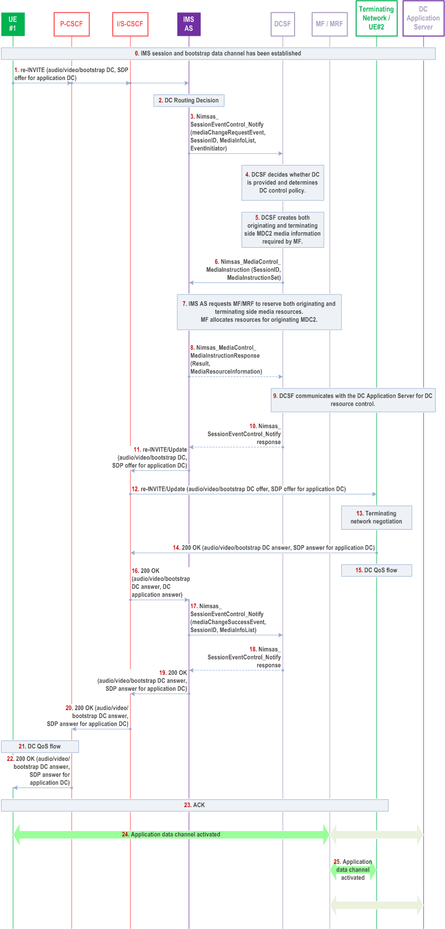
AC.7.2.3 Person-to-Application and Application-to-Person (P2A2P) Procedure p. 380
This procedure enables originating and terminating UE to establish application data channels for the same application to communicate with the same Data Channel Application Server.
The P2A2P procedure requires the establishment of application data channels from UE#1 to MF and from UE#2 to MF. The two application data channels are associated with the same application. This enables UE#1 and UE#2 to interact with the same DC Application Server simultaneously and the DC Application Server to correlate the data exchanged with both UEs. The P2A procedures as described in clause AC.7.2 are used to establish one application data channel between UE#1 and MF and, for A2P scenario, one application data channel between UE#2 and MF. In case of two involved UEs, this enables independent communication between UE#1 and UE#2 with the DC Application Server.

Step 0.
IMS session and bootstrap data channels are established. Selected data channel applications are downloaded to UE#1 and possibly UE#2.
Step 1.
UE#1 sends SIP re-INVITE request with an updated SDP to IMS AS. The updated SDP contains the bootstrap data channel, the application data channel information and associated DC application binding information.
Step 2.
IMS AS validates the data channel media description information and/or user subscription data to determine whether the DCSF needs to be notified.
Step 3.
IMS AS selects and notifies the DCSF about the call event and data channel establishment request.
Step 4.
The DCSF determines how to process the application data channel establishment request based on the parameters (i.e. associated DC application binding information) in the notification from IMS AS and/or DCSF service specific policy.
Step 5.
DCSF determines that the added application data channel media in the SDP offer requires the DC Application Server is the endpoint for both originating and terminating UE and that the application DC must be anchored at the MF or MRF. DCSF communicates with the DC Application Server for DC resource control. Once the application data channel is established, the DC Application Server will send/receive traffic to/from UE#1 through the MDC2 interface.
Step 6.
DCSF invokes Nimsas_MediaControl service to send data channel control request to IMS AS, including information how to relay data channel media via the MDC2 interface.
Step 7.
IMS AS reserves data channel media resources at the MF via DC2 or at the MRF via Mr'/Cr based on the DC media information received from DCSF. These requests by the IMS AS, are used to create two associated resources (one for the originating UE, and one for the terminating UE) in the MF/MRF.
Step 8.
IMS AS notifies the DCSF about MediaControl instruction control response.
Step 9.
DCSF communicates with the DC Application Server for DC resource control and provides information on data channel media resources reserved at the MF.
Step 10.
The DCSF stores the media resource information and replies to the Nimsas notification request.
Step 11-12.
IMS AS sends re-INVITE which include the SDP offer from MF or MRF for the application data channel to the originating S-CSCF and then to the remote network and UE#2.
Step 13-16.
UE#2 and terminating network return 200 OK with SDP answer for audio/video and for the application data channel. The terminating network P-CSCF executes QoS procedure for application data channel media based on the SDP in the 200 OK. Based on the received DC Application binding information in the re-INVITE, UE#2 may need to download the corresponding DC Application signalled in the SDP offer, if not done already and associate it with the requested application DC.
Step 17.
IMS AS notifies the DCSF about the successful result of the MediaChangeRequest event.
Step 18.
DCSF updates media resources in the MF/MRF via IMS AS.
Step 19.
DCSF replies to the notification received in step 17.
Step 20-21.
The IMS AS includes SDP answer for application data channel to UE#1 in 200 OK and sends 200 OK to S-CSCF and P-CSCF.
Step 22.
The originating network P-CSCF executes QoS procedure for application data channel media based on the SDP in the 200 OK.
Step 23.
P-CSCF returns the 200 OK to UE#1.
Step 24.
UE#1 sends ACK to the terminating network.
Step 25.
The application data channel between UE#1 and DC Application Server is established via MF or MRF. MF or MRF forwards data channel traffic between UE#1 and DC Application Server via MDC2.
Step 26.
The application data channel between UE#2 and DC Application Server is established via MF or MRF. MF or MRF forwards data channel traffic between UE#2 and DC Application Server via MDC2.