TS 23.501
System Architecture for the 5G System
V19.0.0 (Wzip)
2024/06 722 p.
V18.6.0 (PDF)
2024/06 718 p.
V17.13.0
2024/06 577 p.
V16.20.0
2024/06 458 p.
V15.13.0
2022/03 253 p.
- Rapporteur:
- Ms. Chandramouli, Devaki
Nokia Germany
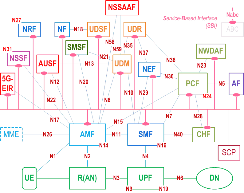
essential Table of Contents for TS 23.501 Word version: 19.0.0
each title, in the "available" or "not available yet" area, links to the equivalent title in the CONTENT
![]()
![]()
editorial Errors in TS 23.501 Word version: 19.0.0
bad references are displayed in this form, followed by the correction
bad references for which a correction was not found are displayed in this form
bad references for which a correction was not found are displayed in this form
- Clause numbering
-
6.3.6.3.3 Combined N3IWF/ePDG Selectionshould be replaced by:6.3.6.4.3 Combined N3IWF/ePDG Selection
- Bad reference in clause 5.15.18.3
-
clause 4.3.4.2 in TS 23.502instead of:clause 4.2.3.4 in TS 23.502
- Bad references in clause 5.34.3
-
clause 4.23 in TS 23.502instead of:clause 23 in TS 23.502
- Bad reference in clause 6.2.21
-
clause 4.4.1ainstead of:clause 5.4.4.1a
- Bad reference in clause 6.3.12.2
-
clause 6.15.2.1
- Bad reference in clause 6.3.6.1
-
clause 6.15.2.1
![]()