Content for TS 23.228 Word version: 19.0.0
1…
3…
4…
4.2.4…
4.3…
4.4…
4.13…
4.16…
5…
5.2…
5.3…
5.4…
5.4.7…
5.4.8…
5.4a…
5.5…
5.5.3…
5.6…
5.6.3…
5.7…
5.7.3…
5.7.5…
5.7.8…
5.8…
5.10…
5.11…
5.11.3…
5.11.3.3
5.11.3.4
5.11.4…
5.11.5…
5.11.5.3…
5.11.6…
5.12…
5.16…
5.16.2…
5.19…
5.20…
A…
E…
E.2.2…
G…
G.5…
H
I…
J…
K…
L…
M…
M.3…
N…
P…
Q…
Q.2.5…
R…
S…
T…
U…
U.2…
V…
W…
X…
Y…
Z…
AA…
AA.3…
AB…
AC…
AC.7…
AC.7.2…
AC.7.2.2
AC.7.2.3…
AC.7.4…
AC.9…
AC.10…
5.19 Support for Transit scenarios in IMS
5.19.1 General
5.19.2 Providing IMS application services in transit network scenarios
...
...
5.19 Support for Transit scenarios in IMS |R7| p. 203
5.19.1 General |R11| p. 203
This clause presents some high level flows to describe the procedures for supporting IMS transit network scenarios.
The IMS Transit Functions perform an analysis of the destination address, and determine where to route the session. The session may be routed directly to an MGCF, BGCF, or to another IMS entity in the same network, to another IMS network, or to a CS domain or PSTN. The address analysis may use public (e.g. DNS, ENUM) and/or private database lookups, and/or locally configured data. As described in clause 4.15 there are various transit configurations possible that may be supported.
For the case where an operator is providing transit functions for other operators and/or enterprise networks, the configuration is as shown in Figure 5.49. The configuration in Figure 5.49 is also intended to cover scenarios where an operator routes traffic from other IMS- or SIP-networks to CS domain or PSTN customers through the IMS transit network. In this case the terminating network as shown in the Figure indicates the operator's CS domain or PSTN.
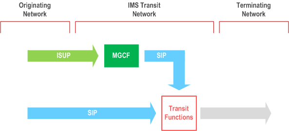
For the transit operator in Figure 5.49, ISUP messages that arrive at a configured MGCF, are translated into SIP, and are passed to the IMS Transit Functions. SIP messages may arrive directly at the configured entity supporting the transit functions or first pass through an IBCF before arriving at the IMS Transit Functions. The IMS Transit Functions determine whether to route directly to an MGCF, BGCF, or to another IP entity on the path (e.g. an IBCF). In this transit operator configuration, the IMS Transit Functions might reside in a stand-alone entity or might be combined with the functionality of an MGCF, a BGCF, an I-CSCF, an S-CSCF or an IBCF. When residing in a stand-alone entity the IMS Transit Functions shall be able to generate CDRs.
For the case where the operator is the terminating network operator handling a terminating service for its own customers, the configuration and operation may be more complex as shown in Figure 5.50.
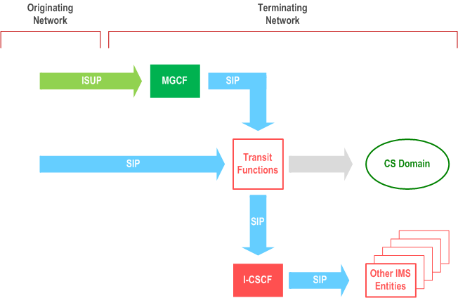
For the operator in Figure 5.50, ISUP messages arriving at an MGCF may be destined for an IMS or a CS domain customer (see clause 4.15). The ISUP messages are translated into SIP.
The operator can choose whether to route all traffic through the IMS Transit Functions, which subsequently route to the I-CSCF for IMS terminating call scenarios or to an MGCF for the case of CS domain subscribers as described above. This is depicted in Figure 5.50. In this case, there may be an additional delay for terminating sessions destined for IMS subscribers.
As an alternative, the operator may choose to route all traffic to the I-CSCF directly and then identify those sessions that are not destined to IMS subscribers based on an HSS query. Based on the response from the HSS, sessions are either routed to an S-CSCF or to the CS domain (optionally via Transit Functions). In this case there may be an additional delay for terminating sessions destined for the CS domain subscribers.
It is the operator's choice to determine which way to route the SIP messages, first through IMS Transit Functions or first to an I-CSCF. This may depend on whether the majority of the sessions that enter the IMS network, are destined to IMS or CS domain subscribers.
In the terminating network configuration shown in Figure 5.50, the IMS Transit Functions might reside in a stand-alone entity or might be combined with the functionality of an MGCF, a BGCF, an I-CSCF, an S-CSCF, or an IBCF. When residing in a stand-alone entity the IMS Transit Functions shall be able to generate CDRs.
For the case where an IMS network serves as a transit network and as a terminating network (depending on the destination of the session), the configuration and operation resembles that of the previous case as shown in Figure 5.50a and Figure 5.50b.
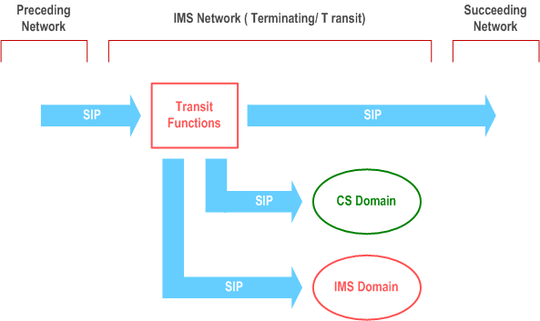
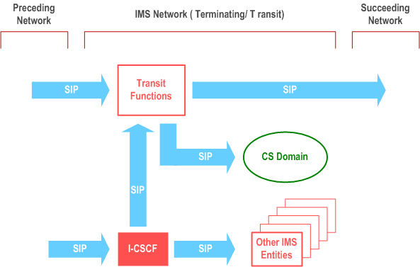
For the operator in Figure 5.50a and Figure 5.50b, ISUP messages arriving at an MGCF may be destined for the own IMS network of for a succeeding network. The ISUP messages are translated into SIP. This is not depicted in Figure 5.50a and Figure 5.50b.
The operator can choose whether to route all traffic through the IMS Transit Functions, which subsequently route to the I-CSCF for sessions destined for subscribers of the own IMS network, to the own CS domain for sessions destined to subscribers of the own CS domain, or to a succeeding network for sessions not destined for subscribers of the own IMS network or the own CS domain. This is depicted in Figure 5.50a. In this case there may be an additional delay for sessions destined to subscribers of the own network.
As an alternative, the operator may choose to route all traffic to the I-CSCF directly and then identify those sessions that are not destined to IMS subscribers of the own IMS network based on an HSS query. Based on the response from the HSS, sessions are either routed to an S-CSCF of the own IMS network or to Transit Functions. The Transit Functions subsequently route the session to either the CS domain of the own network or to a succeeding network. This is depicted in Figure 5.50b. In this case there may be an additional delay for sessions not destined to subscribers of the own IMS network.
It is the operator's choice to determine which way to route the SIP messages, first through IMS Transit Functions or first to an I-CSCF. This may depend on whether the majority of the sessions that enter the IMS network, are destined to subscribers of the own IMS network or not. This operator's choice may be implemented as a functionality of an entry functions such as an IBCF.
In the terminating/transit network configuration shown in Figure 5.50a and Figure 5.50b, the IMS Transit Functions might reside in a stand-alone entity or might be combined with the functionality of an MGCF, a BGCF, an I-CSCF, an S-CSCF, or an IBCF. When residing in a stand-alone entity the IMS Transit Functions shall be able to generate CDRs.
5.19.2 Providing IMS application services in transit network scenarios |R11| p. 206
This clause provides an overview of how IMS application services in transit network scenarios are provided.
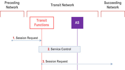
The procedure for IMS application services in transit network is as follows:
Step 1.
The Transit function receives an incoming request from a preceding network.
Step 2.
Based on local configured Transit invocation criteria, the Transit function determines whether one or more services are to be performed.
If the preceding network is the served network, for which special services are invoked, the invocation criteria will trigger and invoke the related services based on the origination of the request.
If the succeeding network is the served network, for which special services are invoked, the invocation criteria will trigger and invoke the related services based on the termination point of the request.
The related service(s) are invoked.
Step 3.
The Transit function performs the transit routing according to clause 5.19.1 and forwards the Session Request towards the succeeding network.