Content for TS 23.228 Word version: 18.6.0
1…
3…
4…
4.2.4…
4.3…
4.4…
4.13…
4.16…
5…
5.2…
5.3…
5.4…
5.4.7…
5.4.8…
5.4a…
5.5…
5.5.3…
5.6…
5.6.3…
5.7…
5.7.3…
5.7.5…
5.7.8…
5.8…
5.10…
5.11…
5.11.3…
5.11.3.3
5.11.3.4
5.11.4…
5.11.5…
5.11.5.3…
5.11.6…
5.12…
5.16…
5.16.2…
5.19…
5.20…
A…
E…
E.2.2…
G…
G.5…
H
I…
J…
K…
L…
M…
M.3…
N…
P…
Q…
Q.2.5…
R…
S…
T…
U…
U.2…
V…
W…
X…
Y…
Z…
AA…
AA.3…
AB…
AC…
AC.7…
AC.7.2…
AC.7.2.2
AC.7.2.3…
AC.7.4…
AC.9…
AC Support of Data Channel services in IMS
AC.1 General
AC.2 Architecture and functions
AC.2.1 Architecture
AC.2.2 Functional entities
AC.2.2.1 Data Channel Signalling Function (DCSF)
AC.2.2.2 Data Channel Application Repository (DCAR)
AC.2.2.3 Data Channel Media Function (MF) / MRF
AC.2.2.4 IMS AS
AC.2.2.5 S-CSCF
AC.2.2.6 HSS
AC.2.3 Reference points
AC.3 IMS Data Channel Service Subscription
AC.4 IMS DC Channel Setup
AC.5 Binding of DC Application with the related DC
AC.6 Data Channel Media Setup
...
...
AC (Normative) Support of Data Channel services in IMS |R18| p. 366
AC.1 General p. 366
This Annex describes IMS architecture enhancements to support data channel services.
Data channels are always established in the context of an IMS MMTel session.
Service based interfaces applicable to data channel services are specified in clauses AA.2.4 and AA.2.5.
The architecture in this annex supports separation of signalling function and media function supporting data channel services. A network function for data channel management signalling, Data Channel Signalling Function (DCSF), is specified. The network function to handle data channel media can be provided in two ways:
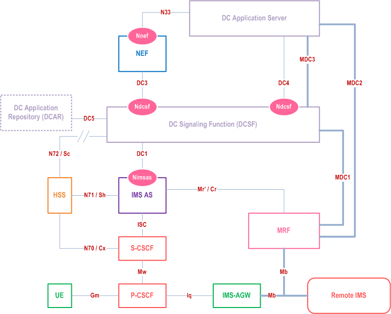
- by enhancing the existing IMS MRF (called MRF) to perform media functions related to DC, which interacts with the IMS AS via enhanced Mr'/Cr interfaces; and
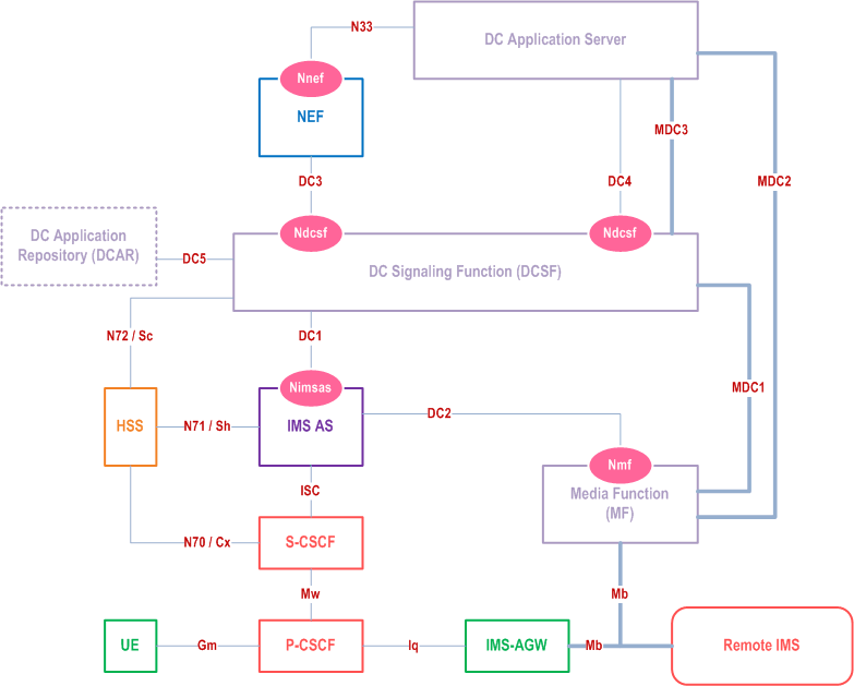
- by introducing a new network function called Media Function (MF), which interacts with the IMS AS via the service-based interface DC2. MF provides media capabilities in support of IMS DC and Augmented Reality.
AC.2 Architecture and functions p. 366
AC.2.1 Architecture p. 366
Figure AC.2.1-1 shows the data channel architecture when using the service-based DC media function.

Figure AC.2.1-2 shows the data channel architecture when using the MRF.

AC.2.2 Functional entities p. 368
AC.2.2.1 Data Channel Signalling Function (DCSF) p. 368
The DCSF is the signalling control function that provides data channel control logic. The DCSF is not involved in SIP signalling. The DCSF supports the following functionalities:
- The DCSF receives event reports from the IMS AS and decides whether data channel service is allowed to be provided during the IMS session;
- The DCSF manages bootstrap data channel and (if applicable) application data channel resources at the MF or MRF via the IMS AS;
- The DCSF supports HTTP web server functionality to download data channel applications (bootstrapping) via MF and/or MRF to the UE based on UE subscription.
- The DCSF downloads data channel applications from the Data Channel Application Repository;
- The DCSF interacts with NEF for data channel capability exposure via N33;
- The DCSF interacts with the DC Application Server for DC resource control via DC4/DC3, and for traffic forwarding via MDC3/MDC2.
- The DCSF interacts with HSS for retrieving and storing DCSF service specific data via N72/Sc.
AC.2.2.2 Data Channel Application Repository (DCAR) p. 369
The Data Channel Application Repository stores the verified data channel applications which are retrieved by the DCSF when required.
AC.2.2.3 Data Channel Media Function (MF) / MRF p. 369
The MF and MRF provide the media resource management and forwarding of data channel media traffic. The MF and MRF provide the following functionalities:
- The MF and MRF manage the data channel media resources (bootstrap and application data channel resources, if applicable) under the control of the IMS AS;
- The MF and MRF terminate the bootstrap data channel from the UE and forward HTTP traffic between the UE and DCSF via MDC1;
- The MF and MRF may anchor the application data channel in P2P scenarios, if required, and forward application data traffic from/to the UEs;
- The MF and MRF relay traffic on the A2P/P2A application data channels between the UE and the DC Application Server via MDC2.
AC.2.2.4 IMS AS p. 369
The IMS AS is enhanced to support the following functionalities:
- The IMS AS interacts with the DCSF via DC1 for event notifications;
- The IMS AS receives the data channel control instructions from the DCSF and accordingly interacts with the MF via DC2 or wit MRF via Mr'/Cr for data channel media resource management;
- The IMS AS interacts with HSS for retrieving and storing DC enhanced IMS AS service specific data via N71/Sh.
AC.2.2.5 S-CSCF p. 369
In addition to the functions defined in clause 4.6.3, the S-CSCF is enhanced to support the following functionalities:
- The S-CSCF includes a Feature-Caps header field indicating its data channel capability in the 200 OK response to the initial and any subsequent REGISTER request from UE.
AC.2.2.6 HSS p. 369
In order to support data channel service, the HSS is additionally enhanced with the following functionalities:
- The HSS stores IMS Data Channel subscription data as transparent data.
- The HSS interacts with DCSF during service data retrieval by DCSF via N72/Sc.
- The HSS interacts with IMS AS during service data retrieval by IMS AS via N71/Sh.
AC.2.3 Reference points p. 370
The following reference points are defined to support data channel service in IMS:
- DC1: Reference point between the DCSF and the IMS AS.
- DC2: Reference point between the IMS AS and MF.
- DC3: Reference point between the DCSF and NEF.
- DC4: Reference point between the DCSF and DC Application Server.
- DC5: Reference point between the DCSF and DCAR.
- N72/Sc: Reference point between the DCSF and HSS.
- N70/Cx/Dx: Reference point between the CSCF and HSS.
- N71/Sh: Reference point between the IMS AS and HSS.
- MDC1: Reference point for transport of data channel media between data channel media function (either MF or MRF) and DCSF.
- MDC2: Reference point for transport of data channel media between data channel media function (either MF or MRF) and DC Application Server.
- MDC3: Reference point for transport of data channel media between DCSF and DC Application Server.
- Mr'/Cr: SIP based reference point between IMS AS and MRF.
AC.3 IMS Data Channel Service Subscription p. 370
Service subscription for IMS Data Channel shall be an extension to the MMTEL related service profile in HSS. The Data Channel subscription data shall be used by the IMS AS and S-CSCF during IMS registration, session initiation or update to authorize subscribers to use the DC service.
IMS AS Service specific data is enhanced with DC specific service data, optionally stored in HSS (e.g. as repository data) and retrieved by IMS AS using N71/Sh interface.
DCSF service specific data used by DCSF for data channel management, may be stored (e.g. as repository data) and retrieved from HSS using the N72/Sc interface. DCSF service specific data are out of scope of 3GPP.
AC.4 IMS DC Channel Setup p. 370
The following principles apply when an IMS Data Channel is established:
- UE can establish an IMS Data Channel simultaneously while establishing an IMS audio/video session or upgrade an ongoing IMS audio/video session through a re-INVITE to an IMS Data Channel session.
- The UE may be configured by the HPLMN either via Device Management or in the UICC whether and when to initiate a DC establishment request. If the UE is not configured by the HPLMN, it is left for UE implementation whether and when to initiate the DC establishment request. The UE shall not initiate a DC establishment request if the network has not indicated support for IMS DC service during IMS registration or if the UE is configured to not establish an IMS Data Channel.
- If a UE that has not subscribed to IMS Data Channel establishes an IMS Data Channel simultaneously with an IMS audio/video IMS session, the IMS AS shall discard the Data Channel request and proceed with the audio/video IMS session establishment.
- The DCSF provides stream ID and a corresponding URL to the MF or MRF via the IMS AS during data channel media resource reservation for the bootstrap data channel that enables downloading a subscriber specific graphical user interface to the UE via the bootstrap data channel. The stream ID is optional. Once the MF or MRF, acting as HTTP proxy, receive a HTTP GET Request containing the root ("/") URL through the bootstrap data channel, the MF or MRF replaces the root ("/") URL in the HTTP GET Request with the subscriber specific URL corresponding to the stream ID (if available) of the bootstrap data channel and forward the request to the DCSF for downloading the subscriber specific graphical user interface to the UE. The MF retrieves the stream ID of the bootstrap data channel from the transport layer of the data channel connection. The UE shall maintain the HTTP session state when interacting with the MF.
AC.5 Binding of DC Application with the related DC p. 371
Information for the binding of DC Application with the related DC is required to support multiple, simultaneous DC applications in a UE.
The binding information is maintained by the HPLMN or retrieved from DC application provider when a DC Application is uploaded to DCSF. DCSF may be configured with a DC application profile associated with the binding information, which indicates the DC control policy (e.g. whether the Application DC establishment follows the P2P, P2A/A2P or P2A2P procedure). The UE receives the binding information of a DC application via the Bootstrap DC, e.g. when the DC application is downloaded to the UE.
When the UE is establishing an IMS Application DC as defined in clause AC.7.2, the binding information is provided by the UE in the attribute of the SDP offer as specified in clause 6.2.13 of TS 26.114. The IMS AS provides the binding information to the DCSF. The DCSF may use the binding information for controlling the Application DC setup.
AC.6 Data Channel Media Setup p. 371
MF and the MRF provides media anchoring when needed for the IMS Bootstrap Data Channel, and the IMS Application Data Channel. To that effect, they support the following capabilities:
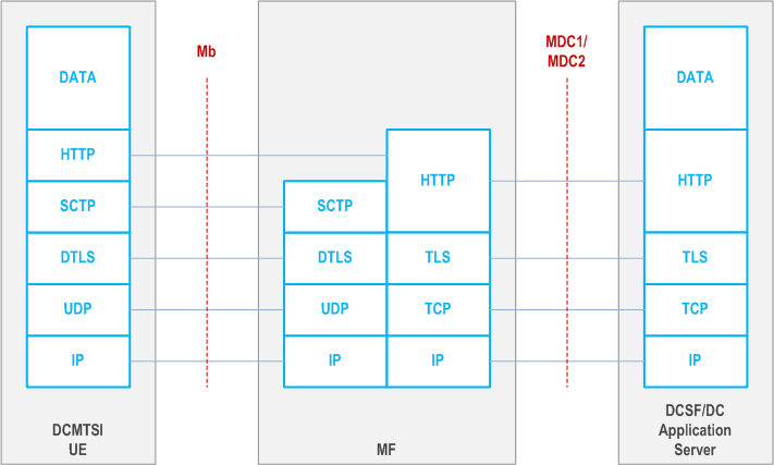
- HTTP Proxy: In this configuration, MF/MRF supports terminating DTLS with HTTP traffic being transparent to MF/MRF. When acting as HTTP Proxy, MF/MRF reserves media resources on both the UE side and on the MDC1/MDC2 side allowing to send HTTP traffic to the DC Application Server. This mode is deployed both for Bootstrap Data Channel, and HTTP Application Data Channels. Figure AC.6-1 illustrates the protocol stack for the HTTP proxy configuration mode for the Bootstrap Data Channel case. When used with HTTP Application Data Channel, the downloaded Data Channel application will in this case communicate with the DC Application Server, using basic HTTP, within the same bootstrap SCTP association as in which this application was downloaded. UDP, TCP and SCTP should be supported as the transport layer protocols for MDC2.

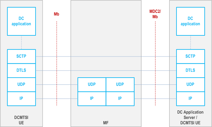
- UDP Proxy: In this configuration, MF/MRF transparently proxies HTTP traffic to its target. When acting as UDP Proxy, the media resources reserved by MF/MRF contain MF/MRF connection information (e.g. IP addresses and port numbers). This mode is deployed only for Application Data Channels. Figure AC.6-2 illustrates the protocol stack for the UDP proxy configuration mode for the Application Data Channel case, providing a Person2Application/Application2Person/Person2Person Data Channel Application.
