Content for TS 23.228 Word version: 19.0.0
1…
3…
4…
4.2.4…
4.3…
4.4…
4.13…
4.16…
5…
5.2…
5.3…
5.4…
5.4.7…
5.4.8…
5.4a…
5.5…
5.5.3…
5.6…
5.6.3…
5.7…
5.7.3…
5.7.5…
5.7.8…
5.8…
5.10…
5.11…
5.11.3…
5.11.3.3
5.11.3.4
5.11.4…
5.11.5…
5.11.5.3…
5.11.6…
5.12…
5.16…
5.16.2…
5.19…
5.20…
A…
E…
E.2.2…
G…
G.5…
H
I…
J…
K…
L…
M…
M.3…
N…
P…
Q…
Q.2.5…
R…
S…
T…
U…
U.2…
V…
W…
X…
Y…
Z…
AA…
AA.3…
AB…
AC…
AC.7…
AC.7.2…
AC.7.2.2
AC.7.2.3…
AC.7.4…
AC.9…
AC.10…
I Border Control Functions
I.1 General
I.2 Overall architecture
I.3 Border Control Functions
I.3.1 IP version interworking
I.3.1.1 Originating Session Flows towards IPv4 SIP network
I.3.1.2 Terminating Session Flows from IPv4 SIP network
I.3.2 Configuration independence between operator networks
I.3.3 Transcoding Support for Interworking
I.3.3.1 General
I.3.3.2 Session Flows
I.3.3.2.1 Proactive transcoding support
I.3.3.2.2 Reactive transcoding support
...
...
I (Normative) Border Control Functions |R7| p. 247
I.1 General p. 247
This annex describes a collection of functions that can be performed on interconnection boundaries between two IM CN subsystem networks or between an IM CN subsystem network and other SIP based multimedia network, based on operator configuration.
I.2 Overall architecture p. 247
Figure I.1 presents a high-level architecture diagram showing how Border Control Functions fit into the IMS architecture.
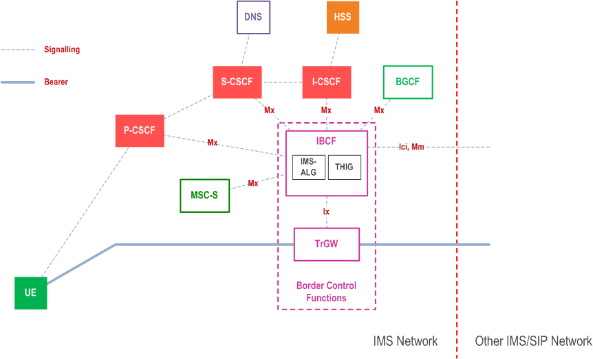
The Mx reference point allows S-CSCF/I-CSCF/P-CSCF/MSC Server enhanced for ICS or MSC Server enhanced for SRVCC to communicate with an IBCF in order to provide border control functions. The functionality of the reference point is specified in TS 24.229.
The Mm reference point allows IBCF to be the entry / exit point towards other IM Core Network Subsystems and provide border control functions. The Ici reference point allows IBCF to be the entry / exit point towards other SIP networks and provide border control functions. The functionality of the reference points are specified in TS 24.229.
The Ix reference point allows the IBCF to control the TrGW. The functionality of Ix is defined in TS 29.162.
I.3 Border Control Functions p. 248
I.3.1 IP version interworking p. 248
The IP version interworking should not adversely affect IMS sessions that do not require IP version interworking.
The network shall, at a minimum, support mechanisms that support IP version interworking for UEs, which comply with previous release of specifications. In addition, any impacts due to specific properties of the IP-CAN shall be taken care of by the IP-CAN itself without affecting the IMS. One possible architecture scenario can be based on the principle defined in TS 23.221 using gateways.
The IMS ALG provides the necessary application function for SIP/SDP protocol stack in order to establish communication between IPv6 and IPv4 SIP applications.
The IMS ALG receives an incoming SIP message from CSCF nodes or from an external IPv4 SIP network. It then changes the appropriate SIP/SDP parameters, translating the IPv6 addresses to IPv4 addresses and vice versa. The IMS ALG needs to modify the SIP message bodies and headers that have IP address association indicated. The IMS ALG will request NA(P)T-PT to provide the bindings data between the different IP addresses (IPv6 to IPv4 and vice versa) upon session initiation, and will release the bindings at session release.
I.3.1.1 Originating Session Flows towards IPv4 SIP network p. 248
The following example session flow shows a scenario where the S-CSCF is responsible for inserting the IMS-ALG in the session path. No I-CSCF node shown in this scenario, if configuration requires presence of an I-CSCF then it would have been collocated with the IMS-ALG.
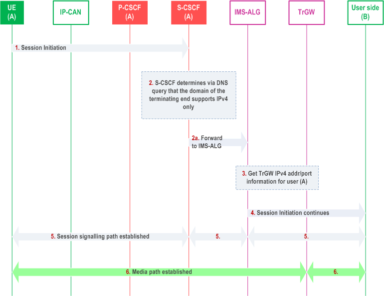
Step 1.
At session release, the IP address/Port information will be released for reuse by other sessions.
UE (A) initiates an IMS session towards User B, via the session path for IMS and the session is analysed at the S-CSCF of UE (A).
Step 2.
S-CSCF for user A determines via DNS (or other mechanism) that the User B's domain cannot be communicated via IPv6 but can be via IPv4.
Step 2a.
S-CSCF forwards the request to IMS-ALG.
Step 3.
The IMS-ALG then acquires the necessary resources from the TrGW such as the IPv4 address and ports on behalf of user A so that User A can communicate with user B transparently.
Step 4.
The IMS-ALG continues IMS signalling towards User B network where User A's IPv6 address/port information is replaced by IPv4 information.
Step 5.
When User (B) responds to the session initiation requests, the IMS-ALG will replace the IPv4 address/port information of User (B) with its own IPv6 information for signalling and with TrGW IPv6 information for the media path as the contact information of User (B) and forward the request to S-CSCF of UE (A). Session signalling path is then established between the UE and the S-CSCF, the S-CSCF and the IMS-ALG, the IMS-ALG and the external network for User B.
Step 6.
The media path is established between the UE (A) and the TrGW, via the IP-CAN, and then between the TrGW and user B.
I.3.1.2 Terminating Session Flows from IPv4 SIP network p. 250
The following session flow shows an example of a terminating session from an IPv4 SIP client towards an IPv6 IMS client. In order for the IPv6 IMS client to be reachable by the IPv4 network, it is assumed that the IPv4 network discovers (via mechanism such as DNS query) the IMS-ALG as the entry point to the IPv6 IMS network.
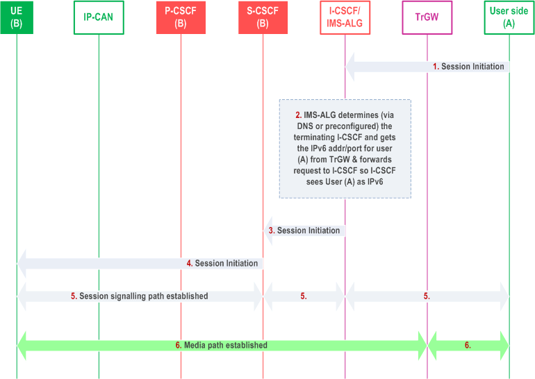
Step 1.
At session release, the IP address/Port information will be released for reuse by other sessions.
In the IMS-ALG, a terminating session is received. IMS-ALG determines either via DNS query or via pre-configuration the appropriate I-CSCF for the user (B) in the IMS network.
Step 2.
IMS-ALG also communicates with TrGW to get the mapping of IPv6 address and ports on behalf of user (A) and replaces the User (A) information in the incoming SIP message and forwards the message towards S-CSCF. From S-CSCF point of view, it continues setting up the IMS session like any other IMS sessions.
Step 3.
The incoming session arrives in the S-CSCF for the user (B).
Step 4.
Session set up continues as usual in the IMS domain towards user (B).
Step 5.
When UE (B) responds to the session initiation requests, the IMS-ALG will replace the IPv6 address/port information of User (B) with its own IPv4 information for signalling and with TrGW IPv4 information for the media path as contact information of UE (B) and forward the request towards the network of User (A). Session signalling path is established between User (B) and S-CSCF, S-CSCF and I-CSCF/IMS-ALG and IMS-ALG and the external User (A)'s network.
Step 6.
Media path is established between UE (B) and the TrGW, via the IP-CAN, and then between the TrGW and User (A).
I.3.2 Configuration independence between operator networks p. 251
The THIG functionality may be used to hide the network topology from other operators. It shall be possible to restrict the following information from being passed outside of an operator's network: addresses of operator network entities.
The specific mechanism chosen needs to take into account the following separate aspects:
Network management:
In the case that network details (i.e. S-CSCF addresses) are visible by other external network elements, any (temporary or permanent) changes to the network topology need to be propagated to network elements outside of the operator's network. This is highly undesirable from a network management perspective.
Network scalability:
Establishing security associations on a pair-wise basis among all CSCFs is likely to be unscalable. The security associations shall be independent of the number of network elements.
Competitively aspects:
The operational details of an operator's network are sensitive business information that operators are reluctant to share with their competitors. While there may be situations (partnerships or other business relations) where the sharing of such information is appropriate, the possibility should exist for an operator to determine whether or not the internals of its network need to be hidden.
Security aspects:
Network element hiding may help to reduce the vulnerability of the overall system to external attacks (e.g. denial of service attacks). Further work is needed in this area.
I.3.3 Transcoding Support for Interworking |R8| p. 251
I.3.3.1 General p. 251
The IBCF/TrGw provides the necessary function for codec transcoding, when required by interworking agreement and session information, in order to establish communication between end points belonging to different IMS domains. These transcoding procedures are applicable to both the originating and the terminating side of the session or (in inter-network scenarios) in a transit network
Transcoding shall only be performed in the case where a common codec cannot be negotiated between the two UEs.
Media transcoding services can be triggered proactively (before the session request is sent to the called UE) or reactively (after the session request has been sent to, and rejected by, the called UE).
The IBCF may allocate a TrGW before sending the SDP Offer to the terminating UE or it may allocate the TrGW upon receiving the SDP answer. The protocol solutions should ensure that the called party is not alerted until resources for transcoding are seized and user plane connection towards the calling party is established to avoid ghost ringing or voice clipping.
If the IBCF is configured per local policy to use proactive transcoding, the IBCF shall add codecs to the offer. When inserting additional codec(s), the network should be able to indicate the preferred codec order.
If the IBCF is configured per local policy to use reactive transcoding, the IBCF shall first determine the codecs supported by the calling and called UEs so that insertion of the TrGW is performed when necessary, if not required for any other interconnect function. This means that the IBCF shall trigger a new offer/answer to the terminating UE, based on the initial offer from the originating UE but including additional codecs supported by the TrGW in the same manner as for the proactive support.
I.3.3.2 Session Flows p. 252
I.3.3.2.1 Proactive transcoding support |R9| p. 252
The following example session flow shows a proactive transcoding support scenario where an IBCF acting as an exit point allocates a TrGW prior to signalling towards the entry point of the other operator's network. The IBCF inserts additional codecs in the SIP signalling. The calling UE capabilities are contained in the SDP offer. Based on the interworking agreement between IM CN subsystems, terminating IBCFs acting as the network entry points may also insert additional codecs in the SIP signalling.
The IBCF and TrGW in Figure I.4 below may be located in the originating network (the IBCF acts as an exit point), or in the terminating network (the IBCF acts as an entry point). There can also be additional IBCF's and TrGW's (not shown) in the case of scenarios involving transit networks.
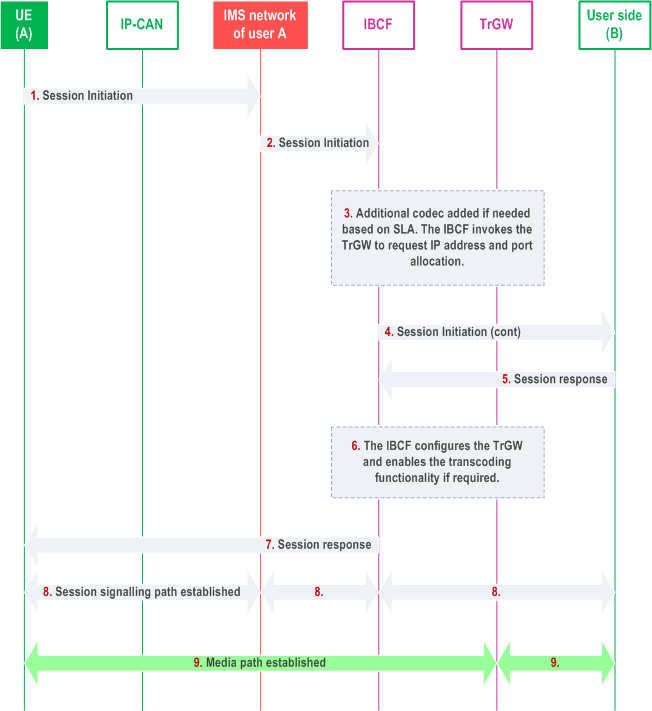
Step 1.
At session release, the codec transcoding resource will be released.
UE (A) initiates an IMS session towards User B, via the session path for IMS and the session is analysed at the IMS network of UE (A).
Step 2.
The IMS network of UE (A) determines that the User B's domain need be communicated via IBCF and forwards the request to the IBCF.
Step 3.
The IBCF checks the SIP message and decides whether additional codec(s) need be inserted into SIP message based on the session information (such as ICSI , SDP) and interworking agreement. When inserting additional codec(s), the network should be able to indicate the preferred codec order. A TrGW is allocated.
Step 4.
The IBCF generates a new SIP message towards User B network based on the received SIP message where additional codec(s) have been added and where the transport address and port information has been altered to indicate the addresses associated by the TrGW.
Step 5.
User (B) selects a codec from the offer modified by IBCF, and responds with an SDP answer.
Step 6.
When receiving the SDP answer, if the IBCF invoked the TrGW in step 3, it now configures the TrGW with address and port towards UE (B). The IBCF checks if the agreed codec belongs to the original offer it received in step 3 or it is one of the codecs that was added by IBCF. If the agreed codec was added by the IBCF, the IBCF configures the TrGW to enable the transcoding functionality. Otherwise, the IBCF will not invoke the transcoding function.
Step 7.
The IBCF generates a new response message back to UE (A) based on the received response message where the codec received from peer side has been replaced with the selected codec.
Step 8.
Session signalling path is established between User (A) and IBCF, IBCF and User (B).
Step 9.
The media path is established between the UE (A) and the TrGW, and then between the TrGW and user B.
I.3.3.2.2 Reactive transcoding support |R9| p. 254
The following example session flow shows a reactive transcoding scenario where IBCF located at the network exit point first determines if a session can be established without addition of transcoding options and, will insert additional codecs in the SIP signalling only after failure to establish a session due to lack of a common codec. Based on the interworking agreement between IM CN subsystems the terminating IBCF may also perform this function.
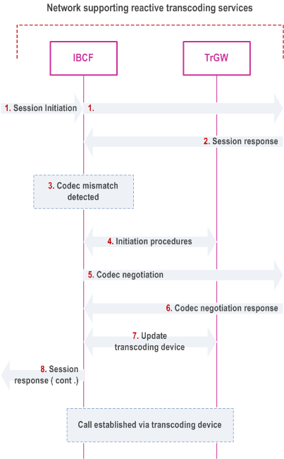
Step 1.
At session release, the codec transcoding resource will be released.
UE (A) initiates an IMS session towards User B, and the session is analysed at the IBCF. The SDP offer is forwarded toward User B without the proactive addition of transcoding options.
Step 2.
A subsequent entity in the signalling path determines that it does not support any codec in the SDP offer and answers with an appropriate error response. This response may include a list of supported codecs.
Step 3.
Based on the response, the IBCF detects the need for reactive transcoding invocation.
Step 4.
The IBCF instructs the TrGW to allocate media processing resources for the session, allocate appropriate transcoding resources for the session and bridge the media flows between the calling and called party endpoints.
Step 5.
Based on the response from the TrGW, the IBCF creates a new SDP offer that contains the codec and transport address information received from the TrGW. If no information about supported codecs was available from the error response, the IBCF may offer all codecs supported by the transcoding device. The IBCF sends this SDP offer towards UE (B).
Step 6.
UE (B) selects a codec and acknowledges the SDP offer with an SDP answer.
Step 7.
Upon receipt of the SDP answer, the IBCF updates the TrGW with the information from the SDP answer.
Step 8.
The IBCF prepares an SDP answer to the SDP offer in step 1, including the selected codec and transport address information for the originating side of the TrGW. The session between the end-points is now established with the media flow traversing the transcoding device.
![]()
![]()
![]()