Content for TS 23.228 Word version: 19.0.0
1…
3…
4…
4.2.4…
4.3…
4.4…
4.13…
4.16…
5…
5.2…
5.3…
5.4…
5.4.7…
5.4.8…
5.4a…
5.5…
5.5.3…
5.6…
5.6.3…
5.7…
5.7.3…
5.7.5…
5.7.8…
5.8…
5.10…
5.11…
5.11.3…
5.11.3.3
5.11.3.4
5.11.4…
5.11.5…
5.11.5.3…
5.11.6…
5.12…
5.16…
5.16.2…
5.19…
5.20…
A…
E…
E.2.2…
G…
G.5…
H
I…
J…
K…
L…
M…
M.3…
N…
P…
Q…
Q.2.5…
R…
S…
T…
U…
U.2…
V…
W…
X…
Y…
Z…
AA…
AA.3…
AB…
AC…
AC.7…
AC.7.2…
AC.7.2.2
AC.7.2.3…
AC.7.4…
AC.9…
AC.10…
4.2.4 IP multimedia Subsystem Service Control Interface (ISC)
4.2.4a HSS to service platform Interface
4.2.4b S-CSCF Service Control Model
4.2.4c I-CSCF to AS reference point (Ma)
4.2.5 The QoS requirements for an IM CN subsystem session
4.2.6 QoS Requirements for IM CN subsystem signalling
4.2.7 Support of SIP forking
4.2.7.1 SIP Forking
4.2.7.2 Forking within and outside the IM CN Subsystem
4.2.7.3 Support for forked requests
...
...
4.2.4 IP multimedia Subsystem Service Control Interface (ISC) p. 32
The ISC interface is between the Serving-CSCF and the service platform(s).
An Application Server (AS) offering value added IM services resides either in the user's home network or in a third party location. The third party could be a network or simply a stand-alone AS.
The Serving-CSCF to AS interface is used to provide services residing in an AS. Two cases were identified:
- Serving-CSCF to an AS in Home Network.
- Serving-CSCF to an AS in External Network (e.g. Third Party or Visited)
(no figure)
Besides the Cx interface the S-CSCF supports only one standardised protocol for service control, which delegates service execution to an Application Server. The protocol to be used on the ISC interface shall be SIP (as defined by RFC 3261, other relevant IETF RFC's, and additional enhancements introduced to support 3GPP's needs on the Mw, Mm, Mg interfaces).
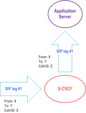
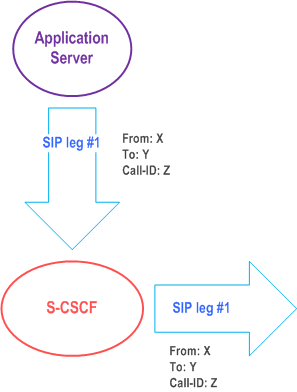
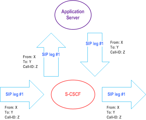
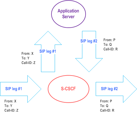
The notion of a "SIP leg" used throughout this specification is identical to the notion of a call leg which is the same as a SIP dialog defined by RFC 3261. The same SIP leg that is received by the S-CSCF on the Mw, Mm and Mg interfaces is sent on the ISC interface. The same SIP leg that is received by the S-CSCF on the ISC interface is sent on the Mw, Mm and Mg interfaces.
Concerning the relationship between the SIP legs of the ISC interface and the SIP legs of the Mw, Mm, and Mg interfaces the S-CSCF acts as a SIP proxy, as shown in Figure 4.3a to Figure 4.3e below.
Figure 4.3a to Figure 4.3e below depict the possible high-level interactions envisioned between the S-CSCF and the Application Server.

4.2.4a HSS to service platform Interface p. 35
The Application Server (SIP Application Server and/or the OSA service capability server and/or IM-SSF) may communicate to the HSS. The Sh and Si interfaces are used for this purpose.
For the Sh interface, the following shall apply:
- The Sh interface is an intra-operator interface.
- The Sh interface is between the HSS and the "SIP Application Server" and between the HSS and the "OSA service capability server". The HSS is responsible for policing what information will be provided to each individual Application Server.
- The Sh interface transports transparent data for e.g. service related data , user related information, etc. In this case, the term transparent implies that the exact representation of the information is not understood by the HSS or the protocol.
- The Sh interface also supports mechanisms for transfer of user related data stored in the HSS (e.g. user service related data, MSISDN, visited network capabilities, UE Time Zone and user location information (e.g. cell global ID/Service Area ID or the address of the serving network element, VPLMN ID, etc.)). The Sh interface supports retrieving the Private User Identities using the same Public User Identity. In the case of a Public User Identity being shared across multiple Private User Identities within the same IMS subscription, the Sh interface supports the transfer of the Private User Identities that share the Public User Identity.
- The Sh interface also supports mechanisms for transfer of standardised data, e.g. for group lists, which can be accessed by different Application Servers. Those Application Servers sharing the data shall understand the data format. This enables sharing of common information between Application Servers, e.g. data managed via the Ut reference point.
- The Sh interface also supports mechanisms that allow Application Servers to activate/deactivate their own existing initial filter criteria stored in the HSS on a per subscriber basis. The Si interface is between the HSS and the IM-SSF. It transports CAMEL subscription information including triggers for use by CAMEL based application services.
4.2.4b S-CSCF Service Control Model p. 36
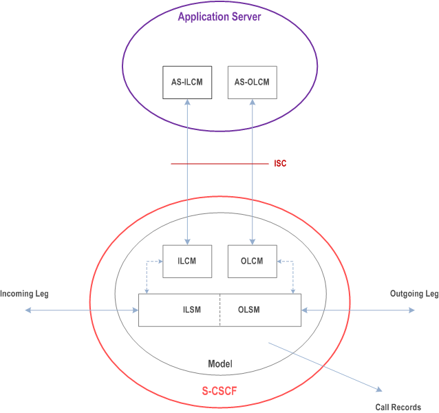
Figure 4.2.4b-1 illustrates the relationship between the S-CSCF and AS. It includes a first-level of modelling inside the S-CSCF and inside the AS. To keep the model simple only one incoming leg and one outgoing leg are shown. In practice a session may consist of more than one incoming leg and/or more than one outgoing leg(s), when using User Agents. An AS may create one or more outgoing legs independent of incoming legs. An AS may create one or more outgoing legs even when there are no incoming legs.
While the above figures show session related flows, the service control model can be applied to other SIP transactions such as registration. Incoming or outgoing leg information e.g. state information, may be passed between the S-CSCF and AS implicitly or explicitly. Implicitly means that SIP information in transit carries information about the state of the session (e.g. an INVITE message received at the S-CSCF on an incoming leg may be sent to the AS with no changes or with some additional information). Explicitly means that SIP information is generated, e.g. to transfer state change information from an S-CSCF to an AS in circumstances where there is no ongoing SIP transaction that can be used. It is a matter for Stage 3 design to determine when to use implicit or explicit mechanisms and to determine what extensions to SIP are necessary.
The internal model of the S-CSCF (shown in Figure 4.2.4b-1) may sometimes exhibit proxy server like behaviour either by passing the requests to the Application Server or by passing the requests out of the system. A Proxy server may maintain session state or not. The S-CSCF may sometimes exhibit User Agent like behaviour. Some Applications require state to be maintained in the S-CSCF. Their exact behaviour depends on the SIP messages being handled, on their context, and on S-CSCF capabilities needed to support the services. It is a matter for Stage 3 design to determine the more detailed modelling in the S-CSCF.
The internal model of the AS (shown in Figure 4.2.4b-1) may exhibit User Agent like behaviour. The exact behaviour depends on the SIP messages being handled and on their context. Detailed Stage 3 modelling for the AS is not required.
The definitions used in the model are:
Combined ILSM OLSM:
Incoming/outgoing Leg State Model: Models the behaviour of an S-CSCF for handling SIP messages on incoming and outgoing session legs. The Combined I/OLSM shall be able to store session state information. It may act on each leg independently, acting as a SIP Proxy, Redirect Server or User Agent dependant on the information received in the SIP request, the filter conditions specified or the state of the session.
It shall be possible to split the application handling on each leg and treat each endpoint differently.
ILCM:
Incoming Leg Control Model: Models the behaviour of an S-CSCF for handling SIP information sent to and received from an AS for an incoming session leg. The ILCM shall store transaction state information.
OLCM:
Outgoing Leg Control Model: Models the behaviour of an S-CSCF for handling SIP information received from and sent to an AS for an outgoing session leg. The OLCM shall store transaction state information.
AS-ILCM:
Application Server Incoming Leg Control Model: Models AS behaviour for handling SIP information for an incoming leg. The AS-ILCM shall store Transaction State, and may optionally store Session State depending on the specific service being executed.
AS-OLCM:
Application Server Outgoing Leg Control Model: Models AS behaviour for handling SIP information for an outgoing leg. The AS-OLCM shall store Transaction State, and may optionally store Session State depending on the specific service being executed.
4.2.4c I-CSCF to AS reference point (Ma) |R8| p. 37
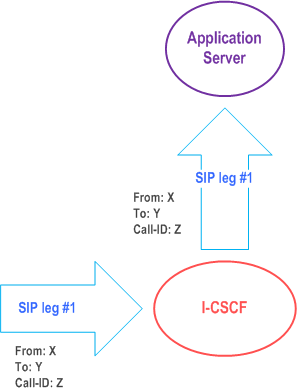
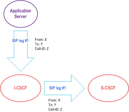
The Ma reference point is between the Interrogating-CSCF and the service platform(s).
The Interrogating-CSCF to AS reference point is used to:
- forward SIP requests destined to a Public Service Identity hosted by an Application Server directly to the Application Server;
- originate a session on behalf of a user or Public Service Identity, if the AS has no knowledge of a S-CSCF assigned to that user or Public Service Identity.
4.2.5 The QoS requirements for an IM CN subsystem session p. 38
The selection, deployment, initiation and termination of QoS signalling and resource allocation shall consider the following requirements so as to guarantee the QoS requirement associated with an IM CN subsystem session.
- Independence between QoS signalling and Session Control The selection of QoS signalling and resource allocation schemes should be independent of the selected session control protocols. This allows for independent evolution of QoS control and the session control in the IM CN subsystem.
- Necessity for End-to-End QoS Signalling and Resource -Allocation End-to-end QoS indication, negotiation and resource allocation during the session set-up in the IM CN subsystem should be enforced for those services and applications that require QoS better than best-effort.
- Void.
- Restricted Resource Access at the IP BS Level Access to the resources and provisioning of QoS at IP BS Level should be authenticated and authorized by applying appropriate QoS policies via the IP Policy Control element
- Restricted Resource Access at the IP-Connectivity Access Network (i.e. layer-2) Level Access to the resources and provisioning of QoS at the IP-Connectivity Access Network Level should be authenticated and authorized by using existing registration/security/QoS policy control mechanisms of the IP-CAN.
-
Co-ordination between Session Control and QoS Signalling/Resource Allocation
- In establishing an IMS session, it shall be possible for an application to request that the resources needed for bearer establishment be successfully allocated before the destination user is alerted.
- In establishing an IMS session, it shall be possible, dependent on the application being offered, to prevent the use of the bearer until the session establishment is completed.
- In establishing an IMS session, it shall be possible for a terminating application to allow the destination user to participate in determining which bearers shall be established.
- Successful bearer establishment shall include the completion of any required end-to-end QoS signalling, negotiation and resource allocation.
- In establishing an IMS session, it shall be possible to use already allocated bearer resources, if these resources fulfil the needs of the session. However, note that QoS policy control mechanisms of the IP-CAN may not allow to use already allocated bearer resources. The initiation of any required end-to-end QoS signalling, negotiation and resource allocation processes at different network segments shall take place after the initiation and delivery of a session set-up request.
- The Efficiency of QoS Signalling and Resource Allocation The sequence of end-to-end QoS signalling, negotiation and resource allocation processes at different network segments should primarily consider the delay in negotiating end-to-end QoS and reserving resources that contributes to the session set-up delay. Parallel or overlapping QoS negotiation and resource reservation shall be allowed where possible.
- Dynamic QoS Negotiation and Resource Allocation Changes (upgrading or downgrading) of QoS provided to an active IMS session shall be supported based on either the request from the IM application or the current network loads or link quality (e.g. radio link quality). It shall be possible to maintain a resource allocation in excess of the resources needed for current media flows (but within the restrictions imposed by points #4 and #5 above), in order to e.g. switch to different media flow characteristics without risk of admission control failure.
- Prevention of Theft of Service The possibility for theft of service in the IM CN subsystem shall be no higher than that for the corresponding packet data and circuit switched services.
- Prevention of Denial of Service The system unavailability due to denial of service attacks in the IM CN subsystem shall be no greater than that for the corresponding packet data and circuit switched services.
4.2.6 QoS Requirements for IM CN subsystem signalling p. 39
Depending on the bearer establishment mode, the UE or the IP-CAN shall be able to establish a dedicated signalling IP-CAN bearer for IM Subsystem related signalling or utilize a general-purpose IP-CAN bearer for IM subsystem signalling traffic.
The use of a dedicated signalling IP-CAN bearer for IM Subsystem related signalling may provide enhanced QoS for signalling traffic.
If a dedicated signalling IP-CAN bearer is to be used for IM Subsystem related signalling, rules and restrictions may apply to the bearer according to operator implementation. A set of capabilities shall be standardised to provide user experience consistency and satisfy user expectation. The rules and restrictions on other capabilities beyond the standardised set are configured by the operator in the IP-CAN.
To enable the described mechanism to work without requiring end-user interaction and under roaming circumstances, it is a requirement for the UE to be made aware of the rules and restrictions applied by the visited network operator. If there is no mechanism available for providing the information about the restrictions back to the UE, the available set of rules and restrictions in this Release is the set of capabilities as defined below.
The dedicated signalling IP-CAN bearer is subject to restrictions, the capabilities to be applied are defined as follows: all messages from the UE that use a dedicated signalling IP-CAN bearer shall have their destination restricted to:
- the P-CSCF assigned for this UE, or to any one of the set of possible P-CSCFs that may be assigned to this UE.
- and towards DHCP and DNS servers within the IMS operator's domain where the P-CSCF is located.
4.2.7 Support of SIP forking p. 40
4.2.7.1 SIP Forking |R6| p. 40
SIP forking is the ability of a SIP proxy server to fork SIP request messages to multiple destinations according to RFC 3261.
4.2.7.2 Forking within and outside the IM CN Subsystem |R6| p. 40
The IM CN subsystem shall have the capability to fork requests to multiple destinations; this capability is subject to rules for forking proxies defined in RFC 3261.
- The S-CSCF shall support the ability for a Public User Identity to be registered from multiple contact addresses, as defined in RFC 3261. The S-CSCF shall support forking so that an incoming SIP request addressed to a Public User Identity is proxied to multiple registered contact addresses. This allows forking across multiple contact addresses of the same Public User Identity.
-
When multiple contact addresses have been registered, then the S-CSCF shall exhibit the following behaviour with regards to forking the incoming SIP request:
- If the UE has indicated capability information upon IMS registration in terms of SIP User Agent capabilities and characteristics described in RFC 3840, then the S-CSCF shall use it to generate a target contact set using the matching mechanism described in RFC 3841. If the UE has not indicated any capabilities for the contact addresses upon registration, then the S-CSCF may still use the preference information, if indicated for the contact addresses upon registration, as described in the following bullet point below.
- If the UE has indicated preference information for contact addresses upon registration, then the S-CSCF shall use it to decide if parallel or sequential forking is used across the contact addresses that have matching callee capabilities, as described in RFC 3261. If the UE has not indicated any preference for the matching contact addresses upon registration, or if the preferences for the matching contact addresses have equal value, then it is up to the configuration of the S-CSCF if parallel or sequential forking is to be performed across the contact addresses that have matching callee capabilities.
- Application Servers in the IMS shall not act as a forking proxy towards the S-CSCF in the sense of RFC 3261.
4.2.7.3 Support for forked requests |R6| p. 41
UE and MGCF shall be ready to receive responses generated due to a forked request and behave according to the procedures specified in RFC 3261 and in this clause.
The UE and MGCF may accept or reject early dialogues from different terminations as described in RFC 3261, for example if the UE is only capable of supporting a limited number of simultaneous dialogs.
Upon the reception of a first final 200 OK (for INVITE), the UE or MGCF shall acknowledge the 200 OK. In addition the UE or MGCF may require updating the allocated resources according to the resources needed. If the UE or MGCF receives a subsequent 200 OK, the UE or MGCF shall acknowledge the dialogue and immediately send a BYE to drop the dialog.
The UE and MGCF may include preferences according to RFC 3841, in INVITE's, indicating that proxies should not fork the INVITE request. The S-CSCF and AS should follow the preferences, if included in the INVITE request. On the terminating side, UE and MGCF shall be able to receive, as specified in RFC 3261, several requests for the same dialog that were forked by a previous SIP entity.
Application Servers and MRFCs shall be capable to handle forked requests according to the procedures specified in RFC 3261.