| |
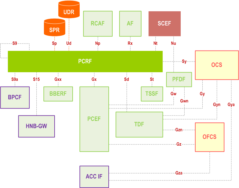
Figure 5.1-1 | Overall PCC logical architecture (non-roaming) when SPR is used |
Figure 5.1-2 | Overall PCC logical architecture (non-roaming) when UDR is used |
Figure 5.1-3 | Overall PCC architecture (roaming with home routed access) when SPR is used |
Figure 5.1-4 | Overall PCC architecture for roaming with PCEF in visited network (local breakout) when SPR is used |
Table 6.1 | Credit re-authorization triggers |
Table 6.2 | Event triggers |
Figure 6.1.7-1 | Scope of the Standardized QCI characteristics for client/server (upper figure) and peer/peer (lower figure) communication |
Table 6.1.7-A | Standardized QCI characteristics |
Table 6.1.7-B | Standardized QCI characteristics |
Figure 6.3 | Relationship of service data flow, packet flow, service data flow template and service data flow filter |
Figure 6.4 | The service data flow template role in detecting the downlink part of a service data flow and mapping to IP-CAN bearers |
Figure 6.5 | The service data flow template role in detecting the uplink part of a service data flow |
Table 6.3 | The PCC rule information |
Table 6.4 | PCC related IP-CAN bearer and IP-CAN session related policy information |
Table 6.4a | TDF session related policy information |
Table 6.4b-1 | PCC specific APN related policy information |
Table 6.5 | The QoS rule information |
Table 6.6 | Usage Monitoring Control related information |
Table 6.7 | The routing rule information |
Table 6.8 | The Application Detection and Control rule information |
Table 6.11 | Traffic steering control information |
Table 6.12 | The NBIFOM routing rule information |
Figure 7.2-1 | IP-CAN Session Establishment |
Figure 7.3.1 | IP-CAN Session Termination |
Figure 7.3.2 | GW (PCEF) Initiated IP-CAN Session Termination |
Figure 7.4 | IP-CAN Session Modification; GW (PCEF) initiated |
Figure 7.5 | IP-CAN Session Modification; PCRF initiated |
Figure 7.6 | Procedure for update of the subscription information in the PCRF |
Figure 7.6-1 | PCRF selection and discovery using DRA |
Figure 7.7.1.1-1 | Gateway Control Session Establishment during Attach |
Figure 7.7.1.2-1 | Gateway Control Session Establishment during BBERF Relocation |
Figure 7.7.2-1 | BBERF-Initiated Gateway Control Session Termination |
Figure 7.7.2-2 | PCRF-Initiated Gateway Control Session Termination |
Figure 7.7.3-1 | Gateway Control and QoS Rules Request |
Figure 7.7.3-2 | Event reporting for PCEF in visited network and locally terminated Gxx interaction |
Figure 7.7.4-1 | Gateway Control and QoS Rules Provision |
Figure 7.9.1 | Initial Spending Limit Report Request |
Figure 7.9.2 | Intermediate Spending Limit Report Request |
Figure 7.9.3 | Final Spending Limit Report Request |
Figure 7.9.4 | Spending Limit Report |
Figure 7.9.5 | Sy Session Termination |
Figure 7.10.1 | RUCI reporting from RCAF to PCRF |
Figure 7.10.2 | PCRF provided reporting restrictions |
Figure 7.10.3 | UE mobility from RCAF1 to RCAF2 in case UE is affected by congestion at RCAF2 after the UE was earlier affected by congestion at RCAF1 |
Figure 7.11.1-1 | Negotiation for future background data transfer |
Figure 7.12.1-1 | PFD Retrieval by the PCEF/TDF |
Figure 7.12.2-1 | Provisioning/update/removal of PFDs in the PCEF/TDF |
Figure A.1 | The GPRS IP-CAN |
Table A.1-1 | GPRS specific credit re-authorization triggers |
Table A.2 | GPRS specific event triggers |
Table A.3 | Recommended mapping for GPRS QoS Class Identifier to/from Release 99 UMTS QoS parameters |
Table A.4 | PCC related IP-CAN bearer and IP-CAN session related policy information |
Table A.4a | TDF session related policy information |
Figure A.4 | The 3GPP EPS IP-CAN (GTP-based) |
Table A.4.3-1 | EPS specific credit re-authorization triggers |
Table A.4.3-2 | EPS specific event triggers |
Table A.4.3.4-1 | PCC related IP-CAN bearer and IP-CAN session related policy information |
Figure D.1.1 | DOCSIS IP-CAN |
Figure D.1.2 | PCC to DOCSIS terminology mapping |
Figure D.2.1 | WiMAX IP-CAN and 3GPP PCC |
Table H.3 | TWAN access specific event/credit reauthorization triggers |
Table H.4 | Untrusted non-3GPP access specific event/credit reauthorization triggers |
Figure N.1-1 | Deployment for sponsored data connectivity |
Figure P.4.2.1-1 | PCC Reference architecture for Fixed Broadband Access Interworking |
Figure P.4.2.2-1 | PCC Reference architecture for Fixed Broadband Access Interworking (home routed) |
Figure P.4.2.3-1 | PCC Reference architecture for Fixed Broadband Access Interworking (visited access) |
Figure P.4.2.4-1 | PCC Reference architecture for Fixed Broadband Access Interworking (non-roaming with non-seamless WLAN offload in Fixed Broadband Access Network) |
Figure P.4.2.5-1 | PCC Reference architecture for Fixed Broadband Access Interworking (roaming with non-seamless WLAN offload in Fixed Broadband Access Network) |
Figure P.4.2.6-1 | PCC Reference architecture for Fixed Broadband Access Interworking (non-roaming with non-seamless WLAN offload in Fixed Broadband Access Network) |
Figure P.4.2.7-1 | PCC Reference architecture for Fixed Broadband Access Interworking (roaming with non-seamless WLAN offload in Fixed Broadband Access Network) |
Table P.5.1-1 | Fixed Broadband specific event triggers |
Figure P.7.2.1 | IP-CAN Session Establishment for both EPC routed and NSWO traffic |
Figure P.7.3.2 | IP-CAN Session Termination for either EPC routed or NSWO traffic |
Figure P.7.4.1 | PCEF-initiated IP-CAN Session Modification |
Figure P.7.4.2 | PCRF-Initiated IP-CAN Session Modification |
Figure P.7.4.3 | BPCF-Initiated IP-CAN Session Modification |
Figure P.7.5.1 | PCRF-triggered Gateway Control Session Establishment for EPC routed traffic |
Figure P.7.5.2 | Gateway Control Session Termination over S9a |
Figure P.7.5.3 | Gateway Control and QoS Rule Request for EPC Routed Traffic |
Figure P.7.5.4 | PCRF-Initiated Gateway Control Session Termination |
Figure P.8.1-1 | S9a CS Session Establishment |
Figure P.8.2-1 | PCRF initiated S9a CS Session Modification |
Figure P.8.2A-1 | BPCF initiated S9a CS Session Modification |
Figure P.8.3-1 | S9a CS Session Termination |
Figure Q.1-1 | Deployment for Usage Monitoring via Online Charging System |
Figure S.4.1.2-1 | PCC Reference architecture for Fixed Broadband Access convergence when SPR is used |
Figure S.4.1.3-1 | PCC Reference architecture for Fixed Broadband Access convergence (roaming) when SPR is used |
Table S.5.1.3-1 | Event triggers |
Table S.5.1.6-1 | Credit re-authorization triggers |
Figure S.8.1 | PCC Reference architecture for Fixed Broadband Access convergence when AAA-based accounting is used |
Figure S.8.2 | PCC Reference architecture for Fixed Broadband Access convergence (roaming) when AAA-based accounting is used |
Figure S.8.8.1 | AAA-based Charging Session Initiation |
Figure S.8.8.2 | AAA-based Charging Session modification |
Figure S.8.8.3.1-1 | AAA-based Charging Session Termination |