Tech-invite3GPPspaceIETFspace
21222324252627282931323334353637384‑5x
Top   in Index   Prev   Next

TS 23.228
IP Multimedia Subsystem (IMS)

V19.2.0 (Wzip)2025/03  480 p.
V18.9.0 (PDF)2025/03  390 p.
V17.3.0  2021/12  355 p.
V16.7.0  2021/12  351 p.
V15.5.0  2021/12  333 p.
V14.7.0  2021/12  322 p.
V13.9.0  2021/12  315 p.
V12.11.0  2021/12  312 p.
V11.11.0  2015/06  292 p.
V10.9.0  2015/06  274 p.
V9.4.0  2010/09  255 p.
V8.12.0  2010/03  250 p.
V7.16.0  2009/12  225 p.
V6.16.0  2007/03  182 p.
V5.15.0  2006/06  133 p.
Rapporteur:
Mr. Towle, Thomas
Qualcomm Incorporated
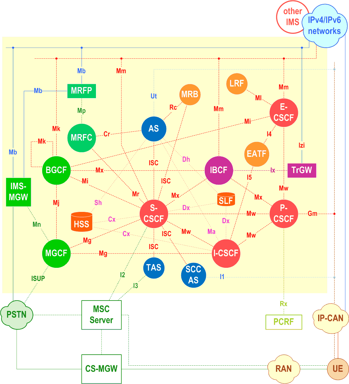
IMS architecture

essential Table of Contents for  TS 23.228  Word version:  19.2.0

each title, in the "available" or "not available yet" area, links to the equivalent title in the CONTENT
Here   Top

Up   Top

List of Figures and Tables

Figure 4.0Reference Architecture of the IP Multimedia Core Network Subsystem
Figure 4.1Service Platform in Home Network
Figure 4.2External Service Platform
Figure 4.3aApplication Server acting as terminating UA, or redirect server
Figure 4.3bApplication Server acting as originating UA
Figure 4.3cApplication Server acting as a SIP proxy
Figure 4.3dApplication Server performing 3rd party call control
Figure 4.3eA SIP leg is passed through the S-CSCF without Application Server involvement
Figure 4.2.4b-1Service Control Model with Incoming Leg Control and Outgoing Leg Control
Figure 4.3fI-CSCF forwarding a SIP request destined to a Public Service Identity to an Application Server hosting this Public Service Identity
Figure 4.3gApplication Server originating a session on behalf of a user or a Public Service Identity, having no knowledge of the S-CSCF to use
Figure 4.5Relationship of the Private User Identity and Public User Identities
Figure 4.6The relation of a shared Public User Identity (Public-ID-2) and Private User Identities
Figure 4.6aThe relationship of Public User Identities, GRUUs and UEs
Figure 4.7Architecture of MRF
Figure 4.13-1IMS applications on top of an IMS communication service
Figure 4.15.3-1IMS application services reference point for transit network scenarios
Figure 5.0aP-CSCF discovery using DHCP and DNS
Figure 5.0bSubscription data updating
Figure 5.0cRelationship of Public User Identities when implicitly registered
Figure 5.0dThe relation of two shared Public User Identities (Public-ID-3 and 4) and Private User Identities
Figure 5.1Registration - User not registered
Figure 5.2Re-registration - user currently registered
Table 5.1Information Storage before, during and after the registration process
Figure 5.3De-registration - user currently registered
Figure 5.4Network initiated application de-registration, registration timeout
Figure 5.5Network initiated application de-registration by HSS, administrative
Figure 5.5aNetwork initiated application de-registration, service platform
Figure 5.5bExample tunnelling of IPv6 traffic over IPv4 networks
Figure 5.6Network based PSTN interworking breakout process
Figure 5.7Bearer establishment showing optional pre-alerting
Figure 5.8Providing service event related information to related endpoint
Figure 5.8aSubscription to event in AS
Figure 5.9Overview of Session Flow Sections
Table 5.2Combinations of session procedures
Figure 5.9aOverview of Session Flow Sections for transit scenarios
Table 5.2aCombinations of IMS transit network procedures
Figure 5.10Serving to serving procedure - different operators
Figure 5.11Serving to serving procedure - same operator
Figure 5.12Serving to PSTN procedure - same operator
Figure 5.13Serving to PSTN procedure - different operator
Figure 5.14Mobile origination procedure - roaming
Figure 5.15Mobile origination procedure - home
Figure 5.16PSTN origination procedure
Figure 5.16aOriginating session from external SIP client
Figure 5.16bApplication Server origination procedure
Figure 5.16cS-CSCF selection by I-CSCF for AS Originating call procedure
Figure 5.17Mobile termination procedure - roaming
Figure 5.18Mobile termination procedure - home
Figure 5.18aMobile Terminating procedures to a user that is unregistered for IMS services but is registered for CS services
Figure 5.19PSTN termination procedure
Figure 5.19bTerminating session towards external SIP client, initiate session set up not requiring precondition capabilities and with inactive media
Figure 5.19cContinuation of terminating session towards external SIP client, session set up with active media
Figure 5.19dIncoming session, direct route towards the AS
Figure 5.19eIncoming session, indirect route to AS via S-CSCF
Figure 5.19fIncoming session, direct route to AS using DNS
Figure 5.19gApplication Server termination
Figure 5.19hEnd-to-end session flow procedure without preconditions - no resource reservation required before session becomes active
Figure 5.20SLF on register (1st case)
Figure 5.20aSLF on register (2nd case)
Figure 5.21SLF on UE invite
Figure 5.21aSLF on AS access to HSS
Figure 5.22Terminal initiated session release
Figure 5.23PSTN initiated session release
Figure 5.26Network initiated session release - P-CSCF initiated - after removal of IP-CAN bearer
Figure 5.27Network initiated session release - S-CSCF initiated
Figure 5.28Mobile to Mobile session hold and resume
Figure 5.29Mobile-initiated Hold and Resume of a Mobile-PSTN Session
Figure 5.29aPSTN-initiated Hold and Resume of a Mobile-PSTN Session
Figure 5.30Codec negotiation during initial session establishment
Figure 5.31Codec or media flow change - same reservation
Figure 5.32Codec or media flow change - new reservation
Figure 5.33Multimedia session flow - addition of another media
Figure 5.34Providing the authenticated Identity of the originating party
Figure 5.35Blocking the identity of the originating party
Figure 5.36Session redirection initiated by S-CSCF to IMS
Figure 5.37Session redirection to PSTN Termination (S-CSCF #2 forwards INVITE)
Figure 5.37aSession redirection to PSTN Termination (REDIRECT to originating UE#1)
Figure 5.38Session redirection initiated by S-CSCF to general endpoint
Figure 5.39Session redirection initiated by P-CSCF
Figure 5.40Session redirection initiated by UE
Figure 5.41Session redirection after bearer establishment
Figure 5.42Refer operation
Figure 5.11.6.2.1-1
Figure 5.11.6.2.2-1
Figure 5.11.6.2.3-1
Figure 5.43Mobile Terminating call procedures to unregistered IMS Public User Identity that has services related to unregistered state
Figure 5.44Mobile Terminating call procedures to unregistered Public User Identity that has no services related to unregistered state
Figure 5.45HSS determination of unknown user
Figure 5.46SLF determination of unknown user
Figure 5.47Immediate Messaging procedure to registered Public User Identity
Figure 5.48Immediate messaging to unregistered Public User Identity, service control invoked
Figure 5.48aMessage session establishment
Figure 5.48bSession based messaging using a chat server
Figure 5.48cSession based messaging with an intermediate node
Figure 5.48dMessage session release procedure
Figure 5.48eMessage session release procedure with intermediate node
Figure 5.49IMS transit network
Figure 5.50Terminating IMS network with transit support, Transit Functions first
Figure 5.50aTerminating/Transit IMS network, Transit Functions first
Figure 5.50bTerminating/Transit IMS network, I-CSCF first
Figure 5.50cIMS application services in transit network
Figure 5.22.1-1Information flow for Overload Control with next-hop monitoring
Figure 5.22.2-1Information flow for AS Overload Control using a filter based mechanism
Figure A.1Information Flow Template
Figure E.1P-CSCF discovery using PDP Context Activation signalling
Figure E.2P-CSCF discovery using EPS bearer activation signalling
Figure E.3Network initiated session release - P-CSCF initiated after loss of radio coverage
Figure G.1Reference model for IMS access when both the signalling and media traverses NAT
Figure G.2Reference model for IMS access when NAT is needed between the IP-CAN and the IMS domain
Figure G.2aReference model for ICE and Outbound Methodology
Figure G.3Session establishment procedure with NAT traversal
Figure G.4Session release procedure with NAT traversal
Figure G.5Packet forwarding in the IMS Access Gateway
Figure G.7Flow Establishment Procedures for Outbound
Figure G.8Session Establishment procedure for NAT Traversal using ICE and Outbound
Figure G.9Session Release Procedure with STUN Relay Resources
Figure H.1HSS functional decomposition
Figure I.1Border Control Functions
Figure I.2Originating IMS session towards an IPv4 end point
Figure I.3Terminating IPv4 SIP session towards an IPv6 IMS user
Figure I.4Proactive transcoding invocation
Figure I.5Reactive transcoding invocation
Figure J.2.1Dynamic User Allocation using Representative AS
Figure J.2.2Bypassing Representative AS procedure
Figure J.3.2.1Assignment of AS via DNS query during first service request
Figure J.3.2.2S-CSCF has stored assigned AS for following service requests
Figure K.1Inter-IMS Network to Network Interface between two IM CN subsystem networks
Figure L.1HSS in 3GPP2
Figure M.1.1.1EPS/5GS architecture for IMS Local Breakout with P-CSCF located in visited network
Figure M.1.1.2Example scenario with P-CSCF located in visited network and IBCF and TrGW in home network
Figure M.2.1.1-1EPS/5GS architecture for IMS Local breakout with P-CSCF located in home network
Figure M.2.1.2Example scenario with P-CSCF located in home network
Figure M.3.1.2Overall architecture for IMS Local Breakout with P-CSCF located in visited network and with VPLMN loopback possibility
Figure M.3.1.3Example scenario with P-CSCF located in visited network and with VPLMN routing
Figure M.3.1.4Example scenario with P-CSCF located in visited network and with home routing
Figure N.1.1Fixed xDSL originating - home (example flow)
Figure N.2.1Fixed xDSL terminating - home (example flow)
Figure P.1.3.2-1Proactive transcoding triggering logic
Figure P.1.3.3-1Reactive transcoding triggering logic
Figure Q.1IMS-ALG bypasses its TrGW and one or more prior TrGWs
Figure Q.2IMS-ALG bypasses its TrGW using secondary realm from prior IMS-ALG
Figure Q.3IMS-ALG bypasses one or more prior TrGWs using a secondary realm
Figure Q.4IMS-ALG bypasses TrGWs performing NAT traversal
Figure Q.5Proactive transcoding where transcoding not required
Figure Q.6IMS-ALG bypasses prior unrequired proactive transcoder
Figure Q.7IMS-ALG bypasses its TrGW and prior unrequired proactive transcoder
Figure Q.8IMS-ALG replaces prior proactive transcoder
Figure R.2-1Mobile origination (user location and/or UE Time Zone information included within INVITE)
Figure R.3-1Mobile origination (user location and/or UE Time Zone information included within Response Confirmation)
Figure R.4-1Mobile termination
Figure R.5-1User location and/or UE Time Zone information Distribution by an IMS AS
Figure R.6-1IMS Session Release
Figure S.2-1High level Static mode business trunking Architecture
Figure S.2.2.2-1Originating procedures for IP-PBXs using static mode business trunking and served by the S-CSCF.
Figure S.2-2Originating procedures for IP-PBXs using static mode business trunking and served by the Transit Function
Figure S.2-3Terminating procedures for IP-PBXs using static mode business trunking and served by the S-CSCF
Figure S.2-4Terminating procedures for IP-PBXs using static mode business trunking and served by the Transit Function
Figure U.1.2-1WebRTC IMS architecture and reference model
Figure U.1.5.1-1Protocol architecture for MSRP
Figure U.1.5.1-2Protocol architecture for MSRP acting as transport relay function
Figure U.1.5.2-1Protocol architecture for BFCP
Figure U.1.5.3-1Protocol architecture for T.140
Figure U.1.5.4-1Protocol architecture for Voice and Video
Figure U.2.1.2-1WIC registration of individual Public User Identity using IMS authentication
Figure U.2.1.3-1WIC registration of individual Public User Identity based on web authentication
Figure U.2.4-1Media plane Optimization
Figure W.2-1IMS traffic home routed
Figure W.4.1-1Subscription by P-CSCF to changes in PLMN ID during initial IMS Registration
Figure W.4.2-1Procedure for PLMN change
Figure W.4.3-1PLMN change detected by EPC/5GC
Figure Y.0-1UDM and HSS collocated or HSS as part of UDM
Figure Y.3Network initiated session release - P-CSCF initiated after loss of radio coverage
Figure Y.9.2-1IMS traffic home routed
Figure Y.9.4-1Subscription by P-CSCF to changes in PLMN ID during initial IMS Registration
Figure Z.3.1-1RLOS IMS Registration procedures for roaming users without roaming agreements with their home network
Figure Z.3.2.1-1Unsuccessful RLOS IMS Registration procedure
Figure AA.1.1-1System Architecture to support SBA in IMS
Figure AA.1.1-2System Architecture to support SBA in IMS in reference point representation
Table AA.2.1.1-1IMS Services provided by an SBI capable HSS
Table AA.2.1.3.1-1IMS Subscriber data types
Table AA.2.1.3.1-2IMS Subscriber data types keys
Table AA.2.2.2-1Cx messages to HSS SBI services and service operations mapping
Table AA.2.2.3-1Sh messages to HSS SBI services and service operations mapping
Table AA.2.4.1-1NF services provided by the IMS AS
Table AA.2.4.2.2-1List of events and Related Optional parameters
Table AA.2.4.4.5-1List of events and related optional parameters
Table AA.2.5.1-1NF services provided by the MF
Figure AA.2.5.2.1-1Media Context Resource Example
Figure AA.3.3.2-1HSS discovery and selection
Figure AB.1.2.1-1Potential deployment architecture for IMS services in SNPN provided by independent IMS provider
Figure AC.2.1-1Architecture option of IMS supporting DC usage with MF
Figure AC.6-1MF "HTTP Proxy" Media Configurations
Figure AC.6-2MF "UDP Proxy" Media Configurations
Figure AC.7.1-1Bootstrap Data Channel set up Signalling Procedure
Figure AC.7.2.1-1Person-to-Person Application Data Channel set up Signalling Procedure
Figure AC.7.2.2-1Person-to-Application (P2A) Application Data Channel set up Signalling Procedure
Figure AC.7.2.3-1Symmetric Application Data Channel Establishment
Figure AC.7.9.1-1Bootstrap Data Channel set up Signalling Procedure for IMS data channel interworking with MTSI UE
Figure AC.7.9.2-1Application Data Channel set up signalling procedure for IMS data channel interworking with MTSI UE via MF
Figure AC.7.9.3-1Application Data Channel set up signalling procedure for IMS data channel interworking with MTSI UE via DC application server
Figure AC.7.9.4-1Application Data Channel set up signalling procedure for IMS data channel interworking with originating MTSI UE via DC application server
Figure AC.7.10.4.1.1-1Multiplexing bootstrap data channels in originating network
Figure AC.7.10.4.1.2-1Multiplexing bootstrap data channels in terminating network
Figure AC.7.10.4.2.1-1Application data channel multiplexing when both originating and terminating networks support data channel multiplexing
Figure AC.7.10.4.2.2-1Application data channel multiplexing when terminating network does not support data channel multiplexing
Figure AC.9.2-1Architecture to support AR communication
Figure AC.9.3.1-1Establishment of UE Centric AR communication session
Figure AC.9.3.2-1Establishment of Network Centric AR communication session
Figure AC.10.2.1-1Originating Standalone Bootstrap DC Setup using PSI
Figure AC.10.2.2-1Originating Standalone IMS DC Session if Application not Available in Originating UE
Figure AC.10.2.3-1Originating Standalone IMS DC Session if Application Available in Originating UE
Figure AC.10.2.4-1Adding MMTel Media to standalone IMS data channel session
Figure AC.10.2.5-1Removing all MMTel Media from IMS data channel session
Figure AC.11.2-1Architecture to support Avatar communication
Figure AC.11.3.1-1Procedures of Avatar ID List Download through Bootstrap Data Channel
Figure AC.11.3.2.1-1Procedures of Sending UE centric IMS Avatar communication
Figure AC.11.3.2.2-1Procedures of Receiving UE centric IMS Avatar communication
Figure AC.11.3.3-1Procedures of network centric IMS Avatar communication
Figure AD.2.1-1Subscribe/Notify Framework for event monitoring in IMS
Table AD.2.5.3-1List of events for monitoring capability
Figure AD.3.1-1IMS AS Instance Registration in HSS
Figure AD.3.2-1SUBSCRIBE/NOTIFY Procedure for Subscriber specific IMS events
Figure AD.3.3-1SUBSCRIBE/NOTIFY Procedure for non-subscriber specific IMS events
Figure AE.2.1.1-1Reference architecture of IMS satellite media plane optimization
Figure AE.5.1-1Session establishment procedure with activation of optimized media routing
Figure AF.2.1-1System architecture to support authorization, signing and verification of third party user identity information in IMS
Table AF.2.2.1-1RCD properties
Figure AF.3-1Procedure for signing and verification of third party user identity information in IMS
Figure AF.4-1IMS user specific properties provisioning procedure
Figure AG.2.1-1Procedure of adding data channel(s) to an existing IMS session
Figure AG.2.2-1Establishment procedure of a standalone data channel session
Figure AG.2.3-1Terminating of a standalone data channel session

Top