Tech-invite3GPPspaceIETFspace
21222324252627282931323334353637384‑5x
Top   in Index   Prev   Next

TS 38.300
5G New Radio —
NR and NG-RAN Overall Description – Stage 2

V18.5.0 (PDF)2025/03  273 p.
V17.12.02025/03  215 p.
V16.19.02025/03  156 p.
V15.20.02025/03  103 p.
Rapporteur:
Mr. SEBIRE, Benoist
Nokia Germany

3GPP 38.300 - NG-RAN Overall Architecture

essential Table of Contents for  TS 38.300  Word version:  18.5.0

each title, in the "available" or "not available yet" area, links to the equivalent title in the CONTENT
Here   Top

Up   Top

List of Figures and Tables

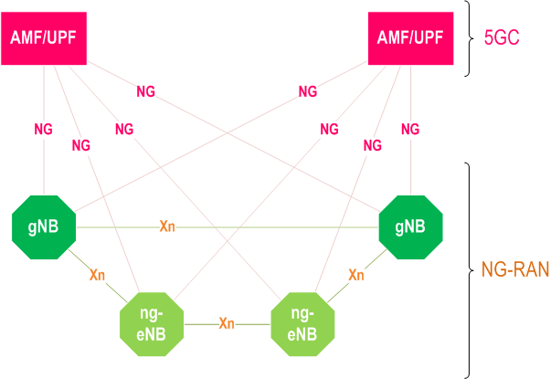
Figure 4.1-1Overall Architecture
Figure 4.2-1Functional Split between NG-RAN and 5GC
Figure 4.3.1.1-1NG-U Protocol Stack
Figure 4.3.1.2-1NG-C Protocol Stack
Figure 4.3.2.1-1Xn-U Protocol Stack
Figure 4.3.2.2-1Xn-C Protocol Stack
Figure 4.4.1-1User Plane Protocol Stack
Figure 4.4.2-1Control Plane Protocol Stack
Figure 4.7.1-1IAB architecture; a) IAB-node using SA mode with 5GC; b) IAB-node using EN-DC
Figure 4.7.1-2Parent- and child-node relationship for IAB-node
Figure 4.7.2-1Protocol stack for the support of F1-U protocol
Figure 4.7.2-2Protocol stack for the support of F1-C protocol
Figure 4.7.2-3Protocol stack for the support of IAB-MT's RRC and NAS connections
Figure 4.7.3.3-1Scheduling of BSR in IAB a) regular BSR based on buffered data, b) Pre-emptive BSR based on UL grant, c) Pre-emptive BSR based on reception of regular BSR
Figure 4.9.1-1Conceptual model of network-controlled repeater
Figure 4.9.5-1Network-Controlled Repeater management
Figure 5.1-1Transmitter block diagram for CP-OFDM with optional DFT-spreading
Table 5.1-15.1-1Supported transmission numerologies
Figure 5.1-2Uplink-downlink timing relation
Figure 5.2.4-1Time-frequency structure of SSB
Table 5.3.3-1Channel coding for uplink control informatio
Table 5.6.2-1Mapping between Channel Access Priority Classes and 5QI
Figure 6.1-1Downlink Layer 2 Structure
Figure 6.1-2Uplink Layer 2 Structure
Figure 6.1-3DL L2-structure for user plane at IAB-donor
Figure 6.1-4DL L2-structure at IAB-node
Figure 6.1-5UL L2-structure at IAB-node
Figure 6.6-1Data Flow Example
Figure 6.7-1Layer 2 Structure for DL with CA configured
Figure 6.7-2Layer 2 Structure for UL with CA configured
Figure 6.10-1BA Example
Figure 6.11.3-1Routing and BH RLC channel selection on BAP sublayer
Table 6.11.3-1Routing configuration
Table 6.11.3-2aBAP header rewriting configuration
Table 6.11.3-2BH RLC channel mapping configuration
Figure 7.3.1-1System Information Provisioning
Figure 9.2.1.3-1UE triggered transition from RRC_IDLE to RRC_CONNECTED
Figure 9.2.1.3-2Rejection of UE triggered transition from RRC_IDLE
Figure 9.2.2.4.1-1UE triggered transition from RRC_INACTIVE to RRC_CONNECTED (UE context retrieval success)
Figure 9.2.2.4.1-2UE triggered transition from RRC_INACTIVE to RRC_CONNECTED (UE context retrieval failure)
Figure 9.2.2.4.1-3Reject from the network, UE attempts to resume a connection
Figure 9.2.2.4.2-1Network triggered transition from RRC_INACTIVE to RRC_CONNECTED
Figure 9.2.2.5-1RNA update procedure with UE context relocation
Figure 9.2.2.5-2Periodic RNA update procedure without UE context relocation
Figure 9.2.2.5-3RNA update procedure with transition to RRC_IDLE
Figure 9.2.2.6-1Resume request responded with Release with Redirect, with UE Context relocation
Figure 9.2.3.1-1Inter-gNB handover procedures
Figure 9.2.3.2.1-1Intra-AMF/UPF Handover
Figure 9.2.3.3-1Re-establishment procedure
Figure 9.2.3.4.2-1Intra-AMF/UPF Conditional Handover
Figure 9.2.3.5.2-1Signalling procedure for LTM
Figure 9.2.4-1Measurement Model
Figure 9.2.5-1Procedure for CN controlled subgrouping
Figure 9.2.5-2Procedure for UE ID based subgrouping
Figure 9.2.6-1Random Access Procedures
Figure 9.2.6-2Fallback for CBRA with 2-step RA type
Figure 11-1DRX Cycle
Figure 12-1QoS architecture
Figure 13.1-15G Key Derivation
Table 13.2-1Security Termination Points
Figure 14-1Feature Set Combinations
Figure 15.3.3.1-1Interaction between gNB and OAM due to ANR
Figure 15.3.3.2-1Automatic Neighbour Relation Function
Figure 15.3.3.5-1Automatic Neighbour Relation Function in case of E-UTRAN detected cell
Figure 16.1.3-1Packet Duplication
Figure 16.2.1.1-1UL or DL bit rate recommendation
Figure 16.2.1.1-2UL or DL bit rate recommendation query
Table 16.3.2.1-1AMF selection based on Temp ID and NSSAI
Figure 16.3.4.2-1AMF selection
Figure 16.3.4.3-1Network Slice-aware Initial Context Setup
Figure 16.3.4.4-1Network Slice-aware PDU Session Resource Setup
Figure 16.3.4.5-1NG based mobility across different Registration Areas
Figure 16.3.4.5-2Xn based mobility across different Registration Areas
Figure 16.8-1Signalling Procedure of UE-side RTT-based PDC
Figure 16.8-2Signalling Procedure of gNB-side RTT-based PDC
Figure 16.8.2-1Signalling procedure of gNB reporting clock quality information to a UE
Figure 16.9.1-1NG-RAN Architecture supporting the PC5 interface
Figure 16.9.2.1-1Control plane protocol stack for SCCH for RRC
Figure 16.9.2.1-2Control plane protocol stack for SCCH for PC5-S
Figure 16.9.2.1-3PC5 control plane (PC5-C) protocol stack for SBCCH
Figure 16.9.2.1-4User plane protocol stack for STCH
Table 16.9.9-1Mapping between Channel Access Priority Classes for SL-U and PQI
Figure 16.10.3-1Downlink Layer 2 Architecture for Multicast Session
Figure 16.10.3-2Downlink Layer 2 Architecture for Broadcast Session
Figure 16.12.2.1-1User plane protocol stack for L2 UE-to-Network Relay
Figure 16.12.2.1-2Control plane protocol stack for L2 UE-to-Network Relay
Figure 16.12.2.2-1User plane protocol stack for L2 UE-to-UE Relay
Figure 16.12.2.2-2Control plane protocol stack for L2 UE-to-UE Relay
Figure 16.12.3-1Protocol Stack of Discovery Message for UE-to-Network/UE-to-UE Relay
Figure 16.12.5.1-1Procedure for L2 U2N Remote UE connection establishment
Figure 16.12.6.1-1Procedure for L2 U2N Remote UE intra-gNB switching from indirect to direct path
Figure 16.12.6.1-2Procedure for L2 U2N Remote UE inter-gNB switching from indirect to direct path
Figure 16.12.6.2-1Procedure for L2 U2N Remote UE intra-gNB switching from direct to indirect path via a L2 U2N Relay UE in RRC_CONNECTED
Figure 16.12.6.2-2Procedure for L2 U2N Remote UE inter-gNB switching from direct to indirect path via a L2 U2N Relay UE in RRC_CONNECTED
Figure 16.12.6.3-1Procedure for L2 U2N Remote UE intra-gNB switching from indirect to indirect path via a target L2 U2N Relay UE in RRC_CONNECTED
Figure 16.12.6.3-2Procedure for L2 U2N Remote UE inter-gNB switching from indirect to indirect path via a target L2 U2N Relay UE in RRC_CONNECTED
Figure 16.12.7-1Procedure for L2 U2U Remote UE connection establishment
Figure 16.14.1-1Overall illustration of an NTN
Figure 16.14.2.1-1Illustration of timing relationship (for collocated gNB and NTN Gateway)
Figure 16.21.2.1-1User plane protocol stack for L2 Multi-path Relay using SL indirect path
Figure 16.21.2.1-2Control plane protocol stack for L2 Multi-path Relay using SL indirect path
Figure 16.21.2.2-1User plane protocol stack for L2 Multi-path Relay using N3C indirect path
Figure 16.21.2.2-2Control plane protocol stack for L2 Multi-path Relay using N3C indirect path
Figure 16.21.3.1-1Procedure for indirect path addition on top of direct path
Figure 16.21.3.1-2Procedure for indirect path change under a single procedure
Figure 16.21.3.1-3Procedure for direct path addition on top of indirect path
Figure 16.21.3.1-4Procedure for direct path change
Figure 18.2-1RA-based SDT with UE context relocation
Figure 18.3-1RA-based SDT without UE context relocation
Figure 18.4-1MT-SDT with/without UE context relocation
Figure A.1-1PDU session establishment
Figure A.2-1DL data with new QFI sent over existing DRB
Figure A.3-1DL data with new QFI sent over existing DRB
Figure A.4-1DL data with new QoS Flow ID sent over new DRB with explicit signalling
Figure A.5-1Release of QoS Flow with Explicit Signalling
Figure A.6-1UL packet with a new QoS flow for which a mapping does not exist in UE
Figure B.1-1Example of Supplementary Uplink
Figure B.2-1Example of multiple SSBs in a carrier
Figure B.4-1NTN based NG-RAN
Table C-1I-RNTI reference profiles
Table D-1gNB local configuration in idle and connected mode for SPID = 252
Table F-1I-RNTI profiles for Full I-RNTI
Table F-2I-RNTI profiles for Short I-RNTI
Figure G-1Components of Mobility Latency
Table G-1Components of Mobility Latency for LTM
Figure G-2Mobility Latency for RACH-based LTM
Figure G-3Mobility Latency for RACH-less LTM

Top