Tech-invite3GPPspaceIETFspace
21222324252627282931323334353637384‑5x
Top   in Index   Prev   Next

TS 23.271
LCS – Location Services

V18.0.0 (PDF)  2024/03  190 p.
V17.0.0  2021/12  190 p.
V16.0.0  2020/06  190 p.
V15.2.0  2019/12  190 p.
V14.4.0  2018/03  187 p.
V13.1.0  2017/12  175 p.
V12.1.0  2014/06  171 p.
V11.3.0  2014/06  171 p.
V10.4.0  2013/03  171 p.
V9.8.0  2013/03  170 p.
V8.1.0  2009/12  146 p.
V7.10.0  2009/12  147 p.
V6.13.0  2005/10  123 p.
V5.13.0  2005/01  82 p.
V4.13.0  2005/01  75 p.
Rapporteur:
Mr. Wong, Gavin
VODAFONE Group Plc

3GPP 23.271 - Location Services (LCS) Architecture

essential Table of Contents for  TS 23.271  Word version:  18.0.0

each title, in the "available" or "not available yet" area, links to the equivalent title in the CONTENT
Here   Top

Up   Top

List of Figures and Tables

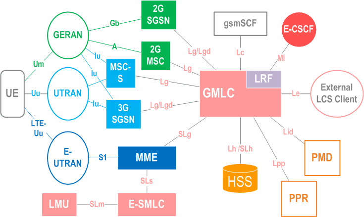
Figure 5.1LCS Access Interfaces and Reference Points
Figure 5.2LCS capability server Functional Diagram
Figure 6.1-1General arrangement of LCS
Figure 6.1-1aGeneral arrangement of LCS for I-WLAN defined in TS 23.234 [52]
Figure 6.1-2General arrangement of LCS with inter-GMLC and LIMS-IWF [Lr] interface
Table 6.1Summary of Functional Groups and Functional Blocks for Location services
Table 6.2Allocation of LCS functional entities to network elements
Table 6.2aAllocation of LCS functional entities to EPS elements
Figure 6.2Generic LCS Logical Architecture
Figure 8.1State Transitions in the GMLC
Figure 8.2State Transitions in the VMSC/MSC Server
Figure 8.3State Transitions in the SGSN
Figure 8.4State Transitions in the MME
Figure 9.1General Network Positioning for a MT-LR
Figure 9.1ANetwork Positioning for an Emergency MT-LR
Figure 9.1BLCS authorisation in PPR
Figure 9.1CPPR notification to GMLC about LCS privacy profile change
Figure 9.1DLCS identity request
Figure 9.2Network Positioning for a CS-MT-LR
Figure 9.3Positioning for a Emergency Services MT-LR without HLR Query
Figure 9.4Positioning for a NI-LR Emergency Service Call
Figure 9.4APositioning for a NI-LR Emergency Service Call using Location Based Routing
Figure 9.5General Network Positioning for Packet Switched MT-LR
Figure 9.5APositioning for a Emergency Services PS-MT-LR without HLR Query
Figure 9.6Network Induced Location Request for the PS Domain
Figure 9.6aGeneral Network Positioning for a Deferred MT-LR with UE available event
Figure 9.6bGeneral Network Positioning for a Combined Periodical/Deferred MT-LR
Figure 9.6cCancellation of a Deferred MT-LR - UE available event procedure
Figure 9.6dDeferred MT-LR procedure for the Area event
Figure 9.7bCancellation of a Deferred MT-LR with change of area event procedure
Figure 9.10CS Post Positioning Notification and Verification Procedure
Figure 9.11PS Post Positioning Notification and Verification Procedure
Figure 9.12Deferred MT-LR Initiation Procedure for Periodic Location
Figure 9.13Reporting of Periodic Location
Figure 9.14LCS Client cancellation of a Deferred MT-LR for Periodic Location
Figure 9.15UE cancellation of a Deferred MT-LR for Periodic Location
Figure 9.16IW-MT-LR in I-WLAN
Figure 9.17IW-MT-LR without an HLR/HSS or AAA Query
Figure 9.18General Network Positioning for EPC-MT-LR
Figure 9.19Positioning for a Emergency Services EPC-MT-LR without HLR Query
Figure 9.20Network Induced Location Request for EPC
Figure 9.21EPC Post Positioning Notification and Verification Procedure
Figure 9.1.19.1-1Deferred EPC-MT-LR procedure for Periodic and Triggered Location
Figure 9.1.19.2-1LCS Client cancellation of a Deferred MT-LR for Periodic and Triggered Location
Figure 9.1.19.3-1UE cancellation of a Deferred MT-LR for Periodic and Triggered Location
Figure 9.7General Network Positioning for CS-MO-LR
Figure 9.8General Network Positioning for packet switched MO-LR
Figure 9.8aDeferred MO-LR Initiation for Periodic Location in CS and PS domain
Figure 9.8bMO-LR for Periodic Self Location with Periodic Positioning in the RAN
Figure 9.8cWLAN UE Originated Procedure in I-WLAN
Figure 9.8dGeneral Network Positioning for packet switched MO-LR
Figure 9.8eUE Assisted and UE Based Positioning and Assistance Delivery Procedure
Figure 9.8fNetwork Assisted and Network Based Positioning Procedure
Figure 9.8gObtaining Network Assisted Data
Figure 9.8hBroadcasting Network Assistance Data
Figure 9.8iDelivery of Ciphering Keys to UEs for Broadcast Assistance Data
Table 9.1LCS Error Recovery Procedures in the VMSC /MSC server for certain Events
Table 9.2LCS Error Recovery Procedures in the SGSN for certain Events
Table 9.4.3aLCS Error Recovery Procedures in the MME for certain Events
Table 9.2aLocation Reconfiguration Requirements for handover of an Emergency PS Bearer or IMS Emergency Call to support Location Continuity (Note 1)
Figure 9.8hxSupport of Location Continuity for Handover of an IMS Emergency Call
Figure 9.8ixLocation Continuity for Handover of an IMS Emergency Call from E-UTRAN to WLAN
Figure 9.8jLocation Continuity for Handover of an IMS Emergency Call from WLAN to E-UTRAN, UTRAN or GERAN
Table 9.3Required UE Subscription Options for MO-LR Requests
Figure 9.9MT-LR procedure for IMS Public User Identities
Table 10.1Logical States for each LCS Privacy Class
Table 10.2LCS data stored in the HLR privacy exception list for an UE Subscriber (or UE Subscriber MSP)
Table 10.3LCS Service types stored in the HLR/HSS per UE subscriber
Table 10.4Logical States for each Mobile Originating LCS Class
Table 10.5Data stored in the HLR for the LCS Mobile Originating List for an UE (or UE Subscriber MSP)
Table 10.6aTemporary LCS data in the HLR
Table 10.6bData stored in the HSS to support broadcast of ciphered assistance data for E-UTRAN access
Table 10.7GMLC Permanent Data for a LCS Client
Table 10.9Logical States for each LCS Privacy Class
Table 10.10LCS data stored in the GMLC/PPR privacy exception list for an UE Subscriber (or UE Subscriber MSP)
Table 10.11LCS Service types stored in the GMLC per UE subscriber
Table 10.12aCodeword handling information stored in the GMLC
Table 10.12bLCS data stored in the GMLC for a UE Subscriber
Table A.1Privacy settings
Figure A.1Privacy Class selection flow diagram
Figure A.2Privacy related action selection flow diagram of the serving node
Table C.1Pseudo-external identities
Table C.2Example of SLPP in HLR/HSS for Call/Session unrelated Class
Table C.3Example of SLPP in HLR/HSS for Call/Session related Class
Table C.4Pseudo-external identity selection at H-GMLC/PPR
Figure E.1GSMA logical model to support anonymity
Figure E.2Logical model to support anonymity
Figure F.1(U)SAT Application Download and Change of Area Event Detection Procedure

Top