Tech-invite3GPPspaceIETFspace
21222324252627282931323334353637384‑5x
Top   in Index   Prev   Next

TS 32.240
Charging Architecture and Principles

V19.3.0 (Wzip)2025/06  … p.
V18.9.0 (PDF)  2024/12  81 p.
V17.11.0  2024/03  70 p.
V16.5.0  2022/03  67 p.
V15.5.0  2019/12  63 p.
V14.4.0  2017/06  59 p.
V13.2.0  2016/06  60 p.
V12.6.0  2014/12  58 p.
V11.7.0  2014/06  48 p.
V10.1.0  2011/04  47 p.
V9.2.0  2011/04  47 p.
V8.6.0  2010/06  47 p.
V7.2.0  2007/03  45 p.
V6.4.0  2006/10  41 p.
Rapporteur:
Mr. Rodrigues, João
Nokia

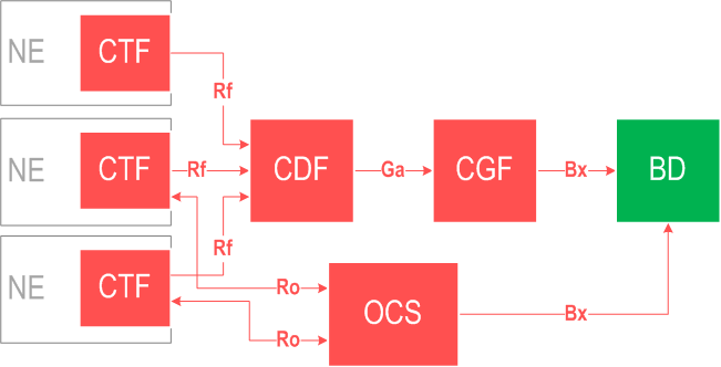
Diameter based offline and online charging applications via Rf and Ro

essential Table of Contents for  TS 32.240  Word version:  19.2.0

each title, in the "available" or "not available yet" area, links to the equivalent title in the CONTENT
Here   Top

Up   Top

List of Figures and Tables

Figure 1.1Charging specifications structure
Figure 4.2.1.1Logical ubiquitous charging architecture and information flows
Figure 4.2.2.1Logical ubiquitous charging architecture and information flows for non-5G systems- reference points
Figure 4.2.3.1Logical ubiquitous charging architecture and information flows for 5G systems - service based representation
Figure 4.2.3.2Logical ubiquitous charging architecture and information flows for 5G systems - reference point representation
Figure 4.2.4.1Logical ubiquitous charging architecture for management domain
Figure 4.2.4.2Logical ubiquitous charging architecture for management domain (MDAS) and control domain (NWDAF)
Figure 4.2.4.3Logical ubiquitous charging architecture for other management layers
Figure 4.3.1.0.1Logical ubiquitous offline charging architecture
Figure 4.3.2.0.1Logical ubiquitous online charging architecture
Figure 4.3.3.0.1Logical ubiquitous converged charging architecture
Figure 4.5.1.1CDF and CGF integrated in the NE
Figure 4.5.1.2CDF integrated in the NE, CGF in a separate physical element
Figure 4.5.1.3CDF and CGF in two separate physical elements
Figure 4.5.1.4CDF and CGF in the same separate physical element
Figure 5.2.1.2.1Possible Configurations of Ga and Bx CDR Formats
Figure 5.4.1Logical diagram illustrating the different parameter categories
Figure B.1.1Voice Control Architecture and Associated Functions
Figure C.4.2.1Logical ubiquitous charging architecture and information flows PCEF located in IP-Edge
Figure D.3.2.1Logical ubiquitous charging architecture and reference points with distributed functional blocks of CTF for offline charging
Figure E.2.1.1High level overall charging architecture and information flows
Figure F.2.1-1Converged charging architecture --- central deployment
Figure F.2.2-0Local/edge deployment option example scenario
Figure F.2.2-1Converged charging architecture --- distributed deployment example scenario

Top