Content for TS 38.413 Word version: 18.2.0
1…
4…
8…
8.2…
8.2.3…
8.3…
8.3.4…
8.4…
8.4.3…
8.5…
8.7…
8.8…
8.10…
8.12…
8.17…
9…
9.2…
9.2.2…
9.2.3…
9.2.4…
9.2.6…
9.2.7…
9.2.9…
9.2.11…
9.2.16…
9.2.17…
9.3…
9.3.1.21…
9.3.1.41…
9.3.1.61…
9.3.1.81…
9.3.1.101…
9.3.1.121…
9.3.1.141…
9.3.1.161…
9.3.1.181…
9.3.1.205…
9.3.1.222…
9.3.1.245…
9.3.2…
9.3.3…
9.3.3.21…
9.3.3.42…
9.3.4…
9.3.4.10…
9.3.5…
9.4…
9.4.4
9.4.5
9.4.6…
9.5…
10…
8.4.3 Handover Notification
8.4.4 Path Switch Request
8.4.5 Handover Cancellation
8.4.6 Uplink RAN Status Transfer
8.4.7 Downlink RAN Status Transfer
8.4.8 Handover Success
8.4.9 Uplink RAN Early Status Transfer
8.4.10 Downlink RAN Early Status Transfer
...
...
8.4.3 Handover Notification p. 76
8.4.3.1 General p. 76
The purpose of the Handover Notification procedure is to indicate to the AMF that the UE has arrived to the target cell and the NG-based handover has been successfully completed. The procedure uses UE-associated signalling.
8.4.3.2 Successful Operation p. 77
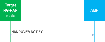
The target NG-RAN node shall send the HANDOVER NOTIFY message to the AMF when the UE has been identified in the target cell and the NG-based handover has been successfully completed.
Interactions with Handover Success procedure:
If the Notify Source NG-RAN Node IE is included in the HANDOVER NOTIFY message, the AMF shall, if supported, notify the source NG-RAN node that the UE has successfully accessed the target NG-RAN node by sending the HANDOVER SUCCESS message.
8.4.3.3 Abnormal Conditions p. 77
Void.
8.4.4 Path Switch Request p. 77
8.4.4.1 General p. 77
The purpose of the Path Switch Request procedure is to establish a UE associated signalling connection to the 5GC and, if applicable, to request the switch of the downlink termination point of the NG-U transport bearer towards a new termination point. The procedure uses UE-associated signalling.
8.4.4.2 Successful Operation p. 77
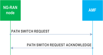
The NG-RAN node initiates the procedure by sending the PATH SWITCH REQUEST message to the AMF. Upon reception of the PATH SWITCH REQUEST message the AMF shall, for each PDU session indicated in the PDU Session ID IE, transparently transfer the Path Switch Request Transfer IE to the SMF associated with the concerned PDU session.
Upon reception of the PATH SWITCH REQUEST message the AMF shall deactivate MT communication handling if already activated, as specified in TS 23.502.
If the RRC Resume Cause IE is included in the PATH SWITCH REQUEST message, the AMF shall, if supported, use it as described in TS 23.502 for User Plane CIoT 5GS Optimisation when the NG-RAN node is an ng-eNB.
If the RedCap Indication IE or the eRedCap Indication IE is included in the PATH SWITCH REQUEST message, the AMF shall, if supported, consider the UE respectively as a RedCap UE or an eRedCap UE that was previously served by a E-UTRA cell, and use the IE according to TS 23.501.
After all necessary updates including the UP path switch have been successfully completed in the 5GC for at least one of the PDU session resources included in the PATH SWITCH REQUEST, the AMF shall send the PATH SWITCH REQUEST ACKNOWLEDGE message to the NG-RAN node and the procedure ends.
The list of accepted QoS flows shall be included in the PATH SWITCH REQUEST message within the Path Switch Request Transfer IE. The SMF shall handle this information as specified in TS 23.502.
For an IAB-MT or a mobile IAB-MT for which the PDU Session ID IE contained in the PATH SWITCH REQUEST message indicates no PDU session identity assigned as defined in TS 24.007, the AMF shall, if supported, consider that the IAB-MT or the mobile IAB-MT, respectively, has no PDU session, and behave as specified in TS 23.501. Subsequently, the NG-RAN node shall, if supported, ignore the PDU Session Resource Switched List IE in the PATH SWITCH REQUEST ACKNOWLEDGE message.
For each PDU session for which the Additional DL QoS Flow per TNL Information IE is included in the Path Switch Request Transfer IE of the PATH SWITCH REQUEST message, the SMF may use each included UP transport layer information as the downlink termination point for the included associated QoS flows for this PDU session split in different tunnels.
The list of PDU sessions which failed to be setup, if any, shall be included in the PATH SWITCH REQUEST message within the Path Switch Request Setup Failed Transfer IE. The AMF shall handle this information as specified in TS 23.502.
For each PDU session for which the User Plane Security Information IE is included in the Path Switch Request Transfer IE of the PATH SWITCH REQUEST message, the SMF shall behave as specified in TS 33.501 and may send back the Security Indication IE within the Path Switch Request Acknowledge Transfer IE of the PATH SWITCH REQUEST ACKNOWLEDGE message.
For each PDU session for which the DL NG-U TNL Information Reused IE set to "true" is included in the Path Switch Request Transfer IE of the PATH SWITCH REQUEST message, the SMF shall, if supported, consider that the DL TNL information contained in the DL NG-U UP TNL Information IE has been reused.
For each PDU session for which the Additional Redundant DL QoS Flow per TNL Information IE is included in the Path Switch Request Transfer IE of the PATH SWITCH REQUEST message, the SMF may use each included UP transport layer information as the downlink termination point for the included associated QoS flows for this PDU session split in different tunnels for the redundant transmission.
For each PDU session for which the Redundant DL NG-U TNL Information Reused IE is included in the Path Switch Request Transfer IE of the PATH SWITCH REQUEST message, the SMF shall, if supported, consider the included DL transport layer address as the DL transport layer address for the redundant transmission as specified in TS 23.501.
For each PDU session for which the Global RAN Node ID of Secondary NG-RAN Node IE is included in the Path Switch Request Transfer IE of the PATH SWITCH REQUEST message, the SMF shall, if supported, handle this information as specified in TS 23.501.
For each PDU session included in the PATH SWITCH REQUEST message, if the Current QoS Parameters Set Index IE is included in the Path Switch Request Transfer IE the SMF shall consider it as the currently fulfilled QoS parameters set among the alternative QoS parameters for the involved QoS flow.
The NG-RAN node shall, if supported, report in the PATH SWITCH REQUEST message the PDU Set based Handling Indicator IE in the Path Switch Request Transfer IE. If the PDU Set based Handling Indicator IE is included in the Path Switch Request Transfer IE in the PATH SWITCH REQUEST message, the SMF shall, if supported, handle this information as specified in TS 23.501.
If the MBS Support Indicator IE is included in the Path Switch Request Transfer IE in the PATH SWITCH REQUEST message, the SMF shall, if supported, handle this information as specified in TS 23.247.
The NG-RAN node shall, if supported, report in the PATH SWITCH REQUEST message the ECN Marking or Congestion Information Reporting Status IE in the Path Switch Request Transfer IE. If the ECN Marking or Congestion Information Reporting Status IE is included in the Path Switch Request Transfer IE in the PATH SWITCH REQUEST message, the SMF shall, if supported, use it to deduce if ECN marking at NG-RAN or ECN marking at UPF or congestion information reporting is active or not active as described in TS 23.501.
If the Security Indication IE is included within the Path Switch Request Acknowledge Transfer IE of the PATH SWITCH REQUEST ACKNOWLEDGE message, the NG-RAN node shall behave as specified in TS 33.501.
If the UL NG-U UP TNL Information IE is included within the Path Switch Request Acknowledge Transfer IE of the PATH SWITCH REQUEST ACKNOWLEDGE message, the NG-RAN node shall store this information and use it as the uplink termination point for the user plane data for this PDU session.
If the Additional NG-U UP TNL Information IE is included within the Path Switch Request Acknowledge Transfer IE of the PATH SWITCH REQUEST ACKNOWLEDGE message, the NG-RAN node shall store this information and use the included UL NG-U UP TNL Information IE(s) as the uplink termination point(s) of the user plane data for this PDU session split in different tunnel.
If the Redundant UL NG-U UP TNL Information IE is included within the Path Switch Request Acknowledge Transfer IE of the PATH SWITCH REQUEST ACKNOWLEDGE message, the NG-RAN node shall, if supported, store this information and use it as the uplink termination point for the user plane data for the redundant transmission for this PDU session as specified in TS 23.501.
If the Additional Redundant NG-U UP TNL Information IE is included within the Path Switch Request Acknowledge Transfer IE of the PATH SWITCH REQUEST ACKNOWLEDGE message, the NG-RAN node shall, if supported, store this information and use the included UL NG-U UP TNL Information IE(s) as the uplink termination point(s) of the user plane data for this PDU session split in different tunnel.
If the CN Packet Delay Budget Downlink IE is included within the Path Switch Request Acknowledge Transfer IE of the PATH SWITCH REQUEST ACKNOWLEDGE message, the NG-RAN node shall, if supported, replace the previously provided CN Packet Delay Budget Downlink if any and use it as specified in TS 23.502.
If the CN Packet Delay Budget Uplink IE is included within the Path Switch Request Acknowledge Transfer IE of the PATH SWITCH REQUEST ACKNOWLEDGE message, the NG-RAN node shall, if supported, replace the previously provided CN Packet Delay Budget Uplink if any and use it as specified in TS 23.502.
If the Burst Arrival Time Downlink IE is included within the Path Switch Request Acknowledge Transfer IE of the PATH SWITCH REQUEST ACKNOWLEDGE message, the NG-RAN node shall, if supported, replace the previously provided value if any and use it as specified in TS 23.502.
If the Core Network Assistance Information for RRC INACTIVE IE is included in the PATH SWITCH REQUEST ACKNOWLEDGE message, the NG-RAN node shall, if supported, store this information in the UE context and use it for the RRC_INACTIVE state decision and RNA configuration for the UE and RAN paging if any for a UE in RRC_INACTIVE state, as specified in TS 38.300. If the MICO All PLMN IE is included in the Core Network Assistance Information for RRC INACTIVE IE the NG-RAN node shall, if supported, consider that the registration area for the UE is the full PLMN and ignore the TAI List for RRC Inactive IE. If the Paging Cause Indication for Voice Service IE is included in the Core Network Assistance Information for RRC INACTIVE IE, the NG-RAN node shall, if supported, store and use it as specified in TS 38.300. If the PEIPS Assistance Information IE is included in the Core Network Assistance Information for RRC INACTIVE IE, the NG-RAN node shall, if supported, store it and use it for paging subgrouping the UE in RRC_INACTIVE state, as specified in TS 38.300. If the CN MT Communication Handling IE is included in the Core Network Assistance Information for RRC INACTIVE IE, the NG-RAN node shall, if supported, store it and may subsequently request, based on implementation, the CN for MT communication handling as described in TS 23.502.
If the CN Assisted RAN Parameters Tuning IE is included in the PATH SWITCH REQUEST ACKNOWLEDGE message, the NG-RAN node may use it as described in TS 23.501.
If the RRC Inactive Transition Report Request IE is included in the PATH SWITCH REQUEST ACKNOWLEDGE message, the NG-RAN node shall, if supported, store this information in the UE context.
If the New Security Context Indicator IE is included in the PATH SWITCH REQUEST ACKNOWLEDGE message, the NG-RAN node shall use the information as specified in TS 33.501.
Upon reception of the PATH SWITCH REQUEST ACKNOWLEDGE message the NG-RAN node shall store the received Security Context IE in the UE context and the NG-RAN node shall use it as specified in TS 33.501.
If the UE Security Capabilities IE is included in the PATH SWITCH REQUEST ACKNOWLEDGE message, the NG-RAN node shall handle it accordingly (TS 33.501).
If the Redirection for Voice EPS Fallback IE is included in the PATH SWITCH REQUEST ACKNOWLEDGE message, the NG-RAN node shall, if supported, store it and use it in a subsequent decision of EPS fallback for voice as specified in TS 23.502.
If the PDU Session Resource Released List IE is included in the PATH SWITCH REQUEST ACKNOWLEDGE message, the NG-RAN node shall release the corresponding QoS flows and regard the PDU session(s) indicated in the PDU Session Resource Released List IE as being released. The appropriate cause value for each PDU session released is included in the Path Switch Request Unsuccessful Transfer IE contained in the PATH SWITCH REQUEST ACKNOWLEDGE message.
If the SRVCC Operation Possible IE is included in the PATH SWITCH REQUEST ACKNOWLEDGE message, the NG-RAN node shall, if supported, store the content of the received SRVCC Operation Possible IE in the UE context and use it as defined in TS 23.216.
If the Enhanced Coverage Restriction IE is included in the PATH SWITCH REQUEST ACKNOWLEDGE message, the NG-RAN node shall, if supported, store this information in the UE context and use it as defined in TS 23.501.
If the Extended Connected Time IE is included in the PATH SWITCH REQUEST ACKNOWLEDGE message, the NG-RAN node shall, if supported, use it as described in TS 23.501.
If the UE Differentiation Information IE is included in the PATH SWITCH REQUEST ACKNOWLEDGE message, the NG-RAN node shall, if supported, store this information in the UE context for further use according to TS 23.501.
If the NR V2X Services Authorized IE is contained in the PATH SWITCH REQUEST ACKNOWLEDGE message, the NG-RAN node shall, if supported, update its NR V2X services authorization information for the UE accordingly. If the NR V2X Services Authorized IE includes one or more IEs set to "not authorized", the NG-RAN node shall, if supported, initiate actions to ensure that the UE is no longer accessing the relevant service(s).
If the LTE V2X Services Authorized IE is contained in the PATH SWITCH REQUEST ACKNOWLEDGE message, the NG-RAN node shall, if supported, update its LTE V2X services authorization information for the UE accordingly. If the LTE V2X Services Authorized IE includes one or more IEs set to "not authorized", the NG-RAN node shall, if supported, initiate actions to ensure that the UE is no longer accessing the relevant service(s).
If the NR A2X Services Authorized IE is contained in the PATH SWITCH REQUEST ACKNOWLEDGE message, the NG-RAN node shall, if supported, update its NR A2X services authorization information for the UE accordingly. If the NR A2X Services Authorized IE includes one or more IEs set to "not authorized", the NG-RAN node shall, if supported, initiate actions to ensure that the UE is no longer accessing the relevant service(s).
If the LTE A2X Services Authorized IE is contained in the PATH SWITCH REQUEST ACKNOWLEDGE message, the NG-RAN node shall, if supported, update its LTE A2X services authorization information for the UE accordingly. If the LTE A2X Services Authorized IE includes one or more IEs set to "not authorized", the NG-RAN node shall, if supported, initiate actions to ensure that the UE is no longer accessing the relevant service(s).
If the NR UE Sidelink Aggregate Maximum Bit Rate IE is included in the PATH SWITCH REQUEST ACKNOWLEDGE message, the NG-RAN node shall, if supported:
- replace the previously provided UE Sidelink Aggregate Maximum Bit Rate, if available in the UE context, with the received value;
- use the received value for the concerned UE's sidelink communication in network scheduled mode for NR V2X services.
- replace the previously provided UE Sidelink Aggregate Maximum Bit Rate, if available in the UE context, with the received value;
- use the received value for the concerned UE's sidelink communication in network scheduled mode for LTE V2X services.
- replace the previously provided NR A2X UE PC5 Aggregate Maximum Bit Rate, if available in the UE context, with the received value;
- use the received value for the concerned UE's sidelink communication in network scheduled mode for NR A2X services.
- replace the previously provided LTE A2X UE PC5 Aggregate Maximum Bit Rate, if available in the UE context, with the received value;
- use the received value for the concerned UE's sidelink communication in network scheduled mode for LTE A2X services.
- replace the previously provided 5G ProSe UE PC5 Aggregate Maximum Bit Rate, if available in the UE context, with the received value;
- use the received value for the concerned UE's sidelink communication in network scheduled mode for 5G ProSe services.
If the RRC Inactive Transition Report Request IE is included in the PATH SWITCH REQUEST ACKNOWLEDGE message and set to "single RRC connected state report" and the UE is in RRC_CONNECTED state, the NG-RAN node shall, if supported, send one RRC INACTIVE TRANSITION REPORT message to the AMF to report the RRC state of the UE.
If the RRC Inactive Transition Report Request IE is included in the PATH SWITCH REQUEST ACKNOWLEDGE message and set to "single RRC connected state report" and the UE is in RRC_INACTIVE state, the NG-RAN node shall, if supported, send to the AMF one RRC INACTIVE TRANSITION REPORT message plus one subsequent RRC INACTIVE TRANSITION REPORT message when the RRC state transitions to RRC_CONNECTED state.
If the RRC Inactive Transition Report Request IE is included in the PATH SWITCH REQUEST ACKNOWLEDGE message and set to "subsequent state transition report", the NG-RAN node shall, if supported, send one RRC INACTIVE TRANSITION REPORT message to the AMF to report the RRC state of the UE and subsequent RRC INACTIVE TRANSITION REPORT messages to report the RRC state of the UE when the UE enters or leaves RRC_INACTIVE state.
Interactions with PDU Session Resource Notify procedure:
If the QoS related parameters (e.g. the CN Packet Delay Budget Downlink IE or the CN Packet Delay Budget Uplink IE) are included in the Path Switch Request Acknowledge Transfer IE of the PATH SWITCH REQUEST ACKNOWLEDGE message, but cannot be succesfully accepted by the NG-RAN node, the NG-RAN node should continue to use the old values received from the source NG-RAN node, if any. The NG-RAN node shall, if supported, send the PDU SESSION RESOURCE NOTIFY message to notify the AMF.
8.4.4.3 Unsuccessful Operation p. 83
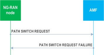
If the 5GC fails to switch the downlink termination point of the NG-U transport bearer towards a new termination point for all PDU session resources, the AMF shall send the PATH SWITCH REQUEST FAILURE message to the NG-RAN node.
The NG-RAN node shall release the corresponding QoS flows and regard the PDU session(s) indicated in the PDU Session Resource Released List IE included in the PATH SWITCH REQUEST FAILURE message as being released.
The appropriate cause value for each PDU session released is included in the Path Switch Request Unsuccessful Transfer IE contained in the PATH SWITCH REQUEST FAILURE message.
8.4.4.4 Abnormal Conditions p. 83
If the AMF receives a PATH SWITCH REQUEST message containing several PDU Session ID IEs (in the PDU Session Resource to be Switched in Downlink List IE) set to the same value, the AMF shall send the PATH SWITCH REQUEST FAILURE message to the NG-RAN node.
If the Partially Allowed NSSAI IE is received in the PATH SWITCH REQUEST ACKNOWLEDGE message and the total number of S-NSSAIs included in the Allowed NSSAI and Partially Allowed NSSAI exceeds eight, the NG-RAN node shall consider the procedure as failed.
If any of the S-NSSAI which is present in the Partially Allowed NSSAI IE is also present in the Allowed NSSAI IE, the NG-RAN node shall consider the procedure as failed.
8.4.5 Handover Cancellation p. 83
8.4.5.1 General p. 83
The purpose of the Handover Cancellation procedure is to enable a source NG-RAN node to cancel an ongoing handover preparation or an already prepared handover. The procedure uses UE-associated signalling.
8.4.5.2 Successful Operation p. 84
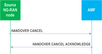
The source NG-RAN node initiates the procedure by sending a HANDOVER CANCEL message to the AMF.
8.4.5.3 Unsuccessful Operation p. 84
Not applicable.
8.4.5.4 Abnormal Conditions p. 84
If the source NG-RAN node becomes aware of the fact that an expected HANDOVER CANCEL ACKNOWLEDGE message is missing, the source NG-RAN node shall consider the Handover Cancellation procedure as successfully terminated.
8.4.6 Uplink RAN Status Transfer p. 84
8.4.6.1 General p. 84
The purpose of the Uplink RAN Status Transfer procedure is to enable lossless NG-based handover. The procedure uses UE-associated signalling.
8.4.6.2 Successful Operation p. 84
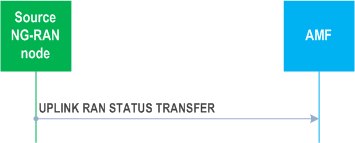
The source NG-RAN node initiates the procedure by stopping the assigning of PDCP-SNs to downlink SDUs and sending the UPLINK RAN STATUS TRANSFER message to the AMF at the point in time when it considers the transmitter/receiver status to be frozen.
For each DRB for which PDCP-SN and HFN status preservation applies, the source NG-RAN node shall include the DRB ID IE, the UL COUNT Value IE and the DL COUNT Value IE within the DRBs Subject to Status Transfer List IE in the RAN Status Transfer Transparent Container IE of the UPLINK RAN STATUS TRANSFER message.
The source NG-RAN node may also include in the UPLINK RAN STATUS TRANSFER message the missing and the received uplink SDUs in the Receive Status of UL PDCP SDUs IE for each DRB for which the source NG-RAN node has accepted the request from the target NG-RAN node for uplink forwarding.
8.4.6.3 Abnormal Conditions p. 85
Void.
8.4.7 Downlink RAN Status Transfer p. 85
8.4.7.1 General p. 85
The purpose of the Downlink RAN Status Transfer procedure is to enable lossless NG-based handover. The procedure uses UE-associated signalling.
8.4.7.2 Successful Operation p. 85
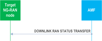
The AMF initiates the procedure by sending the DOWNLINK RAN STATUS TRANSFER message to the target NG-RAN node. The target NG-RAN node using Full Configuration for this handover as per TS 38.300 shall ignore the information received in this message.
For each DRB in the DRBs Subject to Status Transfer List IE within the RAN Status Transfer Transparent Container IE, the target NG-RAN node shall not deliver any uplink packet which has a PDCP-SN lower than the value of the UL Count Value IE.
For each DRB in the DRBs Subject to Status Transfer List IE within the RAN Status Transfer Transparent Container IE, the target NG-RAN node shall use the value of the DL COUNT Value IE for the first downlink packet for which there is no PDCP-SN yet assigned.
If the Receive Status of UL PDCP SDUs IE is included for at least one DRB in the RAN Status Transfer Transparent Container IE of the DOWNLINK RAN STATUS TRANSFER message, the target NG-RAN node may use it in a Status Report message sent to the UE over the radio interface.
8.4.7.3 Abnormal Conditions p. 85
If the target NG-RAN node receives this message for a UE for which no prepared handover exists at the target NG-RAN node, the target NG-RAN node shall ignore the message.
8.4.8 Handover Success |R16| p. 85
8.4.8.1 General p. 85
The Handover Success procedure is used during a DAPS Handover, to inform the source NG-RAN node that the UE has successfully accessed the target NG-RAN node. The procedure uses UE-associated signalling.
8.4.8.2 Successful Operation p. 86
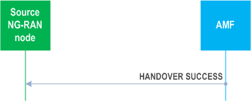
The AMF initiates the procedure by sending the HANDOVER SUCCESS message to the source NG-RAN node.
8.4.8.3 Abnormal Conditions p. 86
If the HANDOVER SUCCESS message refers to a context that does not exist, the source NG-RAN node shall ignore the message.
8.4.9 Uplink RAN Early Status Transfer |R16| p. 86
8.4.9.1 General p. 86
The purpose of the Uplink RAN Early Status Transfer procedure is to transfer the COUNT of the first downlink SDU that the source NG-RAN node forwards to the target NG-RAN node, from the source NG-RAN node to the target NG-RAN node via the AMF during NG DAPS Handover, or the COUNT for discarding of already forwarded downlink SDUs for respective DRB(s) during NG-based handover with time-based trigger condition. The procedure uses UE-associated signalling.
8.4.9.2 Successful Operation p. 86
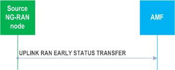
The source NG-RAN node initiates the procedure by sending the UPLINK RAN EARLY STATUS TRANSFER message to the AMF when it considers at least a DRB to be simultaneously served by the source and the target NG-RAN nodes during NG DAPS Handover or sending the UPLINK RAN EARLY STATUS TRANSFER message to the AMF after it initiated a handover preparation with time-based trigger condition.
For each DRB for which DAPS Handover applies, the source NG-RAN node shall include the DRB ID IE and the FIRST DL COUNT Value IE within the DRBs Subject To Early Status Transfer Item IE in the Early Status Transfer Transparent Container IE of the UPLINK RAN EARLY STATUS TRANSFER message.
8.4.9.3 Abnormal Conditions p. 86
Void.
8.4.10 Downlink RAN Early Status Transfer |R16| p. 87
8.4.10.1 General p. 87
The purpose of the Downlink RAN Early Status Transfer procedure is to transfer the COUNT of the first downlink SDU that the source NG-RAN node forwards to the target NG-RAN node, from the source NG-RAN node to the target NG-RAN node via the AMF during NG DAPS Handover, or the COUNT for discarding of already forwarded downlink SDUs for respective DRB during NG-based handover with time-based trigger condition. The procedure uses UE-associated signalling.
8.4.10.2 Successful Operation p. 87
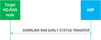
The AMF initiates the procedure by sending the DOWNLINK RAN EARLY STATUS TRANSFER message to the target NG-RAN node.
For each DRB for which the FIRST DL COUNT Value IE is received in the DOWNLINK RAN EARLY STATUS TRANSFER message, the target NG-RAN node shall use it as the COUNT of the first downlink SDU that the source NG-RAN node forwards to the target NG-RAN node.
For each DRB for which the DISCARD DL COUNT Value IE is received in the DOWNLINK RAN EARLY STATUS TRANSFER message, the target NG-RAN node does not transmit forwarded downlink SDUs to the UE whose COUNT is less than the provided DISCARD DL COUNT Value IE and discards them if transmission has not been attempted.
8.4.10.3 Abnormal Conditions p. 87
If the target NG-RAN node receives this message for a UE for which no prepared handover exists at the target NG-RAN node, the target NG-RAN node shall ignore the message.
![]()
![]()
![]()