Content for TS 38.413 Word version: 18.2.0
1…
4…
8…
8.2…
8.2.3…
8.3…
8.3.4…
8.4…
8.4.3…
8.5…
8.7…
8.8…
8.10…
8.12…
8.17…
9…
9.2…
9.2.2…
9.2.3…
9.2.4…
9.2.6…
9.2.7…
9.2.9…
9.2.11…
9.2.16…
9.2.17…
9.3…
9.3.1.21…
9.3.1.41…
9.3.1.61…
9.3.1.81…
9.3.1.101…
9.3.1.121…
9.3.1.141…
9.3.1.161…
9.3.1.181…
9.3.1.205…
9.3.1.222…
9.3.1.245…
9.3.2…
9.3.3…
9.3.3.21…
9.3.3.42…
9.3.4…
9.3.4.10…
9.3.5…
9.4…
9.4.4
9.4.5
9.4.6…
9.5…
10…
8.8 Configuration Transfer Procedures
8.8.1 Uplink RAN Configuration Transfer
8.8.2 Downlink RAN Configuration Transfer
8.9 Warning Message Transmission Procedures
8.9.1 Write-Replace Warning
8.9.2 PWS Cancel
8.9.3 PWS Restart Indication
8.9.4 PWS Failure Indication
...
...
8.8 Configuration Transfer Procedures p. 106
8.8.1 Uplink RAN Configuration Transfer p. 106
8.8.1.1 General p. 106
The purpose of the Uplink RAN Configuration Transfer procedure is to transfer RAN configuration information from the NG-RAN node to the AMF. The AMF does not interpret the transferred RAN configuration information. This procedure uses non-UE associated signalling.
8.8.1.2 Successful Operation p. 107
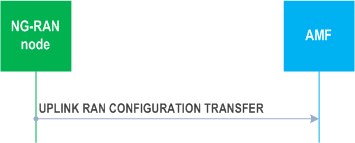
The NG-RAN node initiates the procedure by sending the UPLINK RAN CONFIGURATION TRANSFER message to the AMF.
If the AMF receives the SON Configuration Transfer IE, it shall transparently transfer the SON Configuration Transfer IE towards the NG-RAN node indicated in the Target RAN Node ID IE which is included in the SON Configuration Transfer IE. If the NR CGI IE is included within the Target RAN Node ID IE, the AMF shall, if supported, ignore the Global RAN Node ID IE within the Target RAN Node ID IE, and use it to identify the target gNB as described in TS 38.300.
If the AMF receives the EN-DC SON Configuration Transfer IE, it shall transparently transfer the EN-DC SON Configuration Transfer IE towards an MME serving the eNB indicated in the Target eNB-ID IE which is included in the EN-DC SON Configuration Transfer IE.
If the AMF receives the Inter-system SON Configuration Transfer IE, it shall transparently transfer the Inter-system SON Configuration Transfer IE towards an MME serving the eNB indicated in the Target eNB-ID IE which is included in the Inter-system SON Configuration Transfer IE.
8.8.1.3 Abnormal Conditions p. 107
Void.
8.8.2 Downlink RAN Configuration Transfer p. 107
8.8.2.1 General p. 107
The purpose of the Downlink RAN Configuration Transfer procedure is to transfer RAN configuration information from the AMF to the NG-RAN node. This procedure uses non-UE associated signalling.
8.8.2.2 Successful Operation p. 107
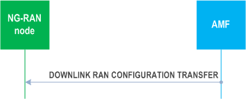
The procedure is initiated with an DOWNLINK RAN CONFIGURATION TRANSFER message sent from the AMF to the NG-RAN node.
If the NG-RAN node receives, in the SON Configuration Transfer IE or in the EN-DC SON Configuration Transfer IE, the SON Information IE containing the SON Information Request IE, it may transfer back the requested information either towards the NG-RAN node indicated in the Source RAN Node ID IE of the SON Configuration Transfer IE or towards an eNB indicated in the Source eNB-ID IE of the EN-DC SON Configuration Transfer IE by initiating the Uplink RAN Configuration Transfer procedure.
If the NG-RAN node receives, in the SON Configuration Transfer IE, the Xn TNL Configuration Info IE containing the Xn Extended Transport Layer Addresses IE, it may use it as part of its ACL functionality configuration actions, if such ACL functionality is deployed.
If the NG-RAN node receives, in the SON Configuration Transfer IE, the SON Information IE containing the SON Information Reply IE including the Xn TNL Configuration Info IE as an answer to a former request, it may use it to initiate the Xn TNL establishment.
In case the IP-Sec Transport Layer Address IE is present and the GTP Transport Layer Addresses IE within the Xn Extended Transport Layer Addresses IE is not empty, GTP traffic is conveyed within an IP-Sec tunnel terminated at the IP-Sec tunnel endpoint given in the IP-Sec Transport Layer Address IE.
In case the IP-Sec Transport Layer Address IE is not present, GTP traffic is terminated at the endpoints given by the list of addresses in the Xn GTP Transport Layer Addresses IE within the Xn Extended Transport Layer Addresses IE.
In case the Xn GTP Transport Layer Addresses IE is empty and the IP-Sec Transport Layer Address IE is present, SCTP traffic is conveyed within an IP-Sec tunnel terminated at the IP-Sec tunnel endpoint given in the IP-Sec Transport Layer Address IE, within the Xn Extended Transport Layer Addresses IE.
In case the Xn SCTP Transport Layer Addresses IE is present and the IP-Sec Transport Layer Address IE is also present, the concerned SCTP traffic is conveyed within an IP-Sec tunnel terminated at the IP-Sec tunnel endpoint given in this IP-Sec Transport Layer Address IE, within the Xn Extended Transport Layer Addresses IE.
If the NG-RAN node receives the SON Information IE containing the SON Information Report IE it may use it as specified in TS 38.300.
If the NG-RAN node receives the Inter-system SON Information IE containing the Inter-system SON Information Report IE it may use it as specified in TS 38.300.
If the NG-RAN node receives the Inter-system SON Information IE containing the Inter-system SON Information Request IE or the Inter-system SON Information Reply IE, it may use it as specified in TS 38.300. If the Reporting System IE in the Inter-system SON Information Request IE is set to "No Reporting", the DOWNLINK RAN CONFIGURATION TRANSFER message shall be ignored.
If the NG-RAN node is configured to use one IPsec tunnel for all NG and Xn traffic (IPsec star topology) then the traffic to the peer NG-RAN node shall be routed through this IPsec tunnel and the IP-Sec Transport Layer Address IE shall be ignored.
8.8.2.3 Abnormal Conditions p. 108
Void.
8.9 Warning Message Transmission Procedures p. 108
8.9.1 Write-Replace Warning p. 108
8.9.1.1 General p. 108
The purpose of Write-Replace Warning procedure is to start or overwrite the broadcasting of warning messages. The procedure uses non UE-associated signalling.
8.9.1.2 Successful Operation p. 109
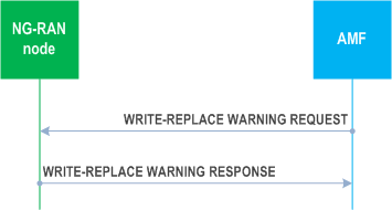
The AMF initiates the procedure by sending a WRITE-REPLACE WARNING REQUEST message to the NG-RAN node.
Upon receipt of the WRITE-REPLACE WARNING REQUEST message, the NG-RAN node shall prioritise its resources to process the warning message.
If, in a certain area, broadcast of a warning message is already ongoing and the NG-RAN node receives a WRITE-REPLACE WARNING REQUEST message with Message Identifier IE and/or Serial Number IE which are different from those in the warning message being broadcast, and if the Concurrent Warning Message Indicator IE is not present, the NG-RAN node shall replace the warning message being broadcast with the newly received one for that area.
If the NG-RAN node receives a WRITE-REPLACE WARNING REQUEST message with a warning message identified by the Message Identifier IE and Serial Number IE and if there are no prior warning messages being broadcast in any of the warning areas indicated in the Warning Area List IE, the NG-RAN node shall broadcast the received warning message for those area(s).
If, in a certain area, broadcast of one or more warning messages are already ongoing and the NG-RAN node receives a WRITE-REPLACE WARNING REQUEST message with a Message Identifier IE and/or Serial Number IE which are different from those in any of the warning messages being broadcast, and if the Concurrent Warning Message Indictor IE is present, the NG-RAN node shall schedule the received warning message for broadcast, for that area.
If the Concurrent Warning Message Indicator IE is present and if a value "0" is received in the Number of Broadcasts Requested IE, the NG-RAN node shall broadcast the received warning message indefinitely until requested otherwise to stop broadcasting, except if the Repetition Period IE is set to "0".
If, in a certain area, broadcast of one or more warning messages are already ongoing and the NG-RAN node receives a WRITE-REPLACE WARNING REQUEST message with Message Identifier IE and Serial Number IE which correspond to one of the warning messages already being broadcast in that area, the NG-RAN node shall not start a new broadcast or replace an existing one but it shall still reply by sending a WRITE-REPLACE WARNING RESPONSE message which includes the Broadcast Completed Area List IE set according to the ongoing broadcast.
If the Warning Area List IE is not included in the WRITE-REPLACE WARNING REQUEST message, the NG-RAN node shall broadcast the indicated message in all of the cells within the NG-RAN node.
If the Warning Type IE is included in the WRITE-REPLACE WARNING REQUEST message, the NG-RAN node shall broadcast the Primary Notification irrespective of the setting of the Repetition Period IE and the Number of Broadcasts Requested IE, and process the Primary Notification according to TS 36.331 and TS 38.331.
If the Data Coding Scheme IE and the Warning Message Contents IE are both included in the WRITE-REPLACE WARNING REQUEST message, the NG-RAN node shall schedule a broadcast of the warning message according to the value of the Repetition Period IE and the Number of Broadcasts Requested IE and process the warning message according to TS 36.331 and TS 38.331.
If the Warning Area Coordinates IE is included in the WRITE-REPLACE WARNING REQUEST message, the NG-RAN node shall include this information together with the warning message being broadcast according to TS 36.331 and TS 38.331.
The NG-RAN node acknowledges the WRITE-REPLACE WARNING REQUEST message by sending a WRITE-REPLACE WARNING RESPONSE message to the AMF.
If the Broadcast Completed Area List IE is not included in the WRITE-REPLACE WARNING RESPONSE message, the AMF shall consider that the broadcast is unsuccessful in all the cells within the NG-RAN node.
8.9.1.3 Unsuccessful Operation p. 110
Not applicable.
8.9.1.4 Abnormal Conditions p. 110
If the Concurrent Warning Message Indicator IE is not present and if a value "0" is received in the Number of Broadcasts Requested IE, the NG-RAN node shall not broadcast the received secondary notification.
If the Concurrent Warning Message Indicator IE is included and if a value "0" is received in the Repetition Period IE, the NG-RAN node shall not broadcast the received warning message except if the Number of Broadcasts Requested IE is set to "1".
If the Concurrent Warning Message Indicator IE is not included and if a value "0" is received in the Repetition Period IE, the NG-RAN node shall not broadcast the received secondary notification except if the Number of Broadcasts Requested IE is set to "1".
8.9.2 PWS Cancel p. 110
8.9.2.1 General p. 110
The purpose of the PWS Cancel procedure is to cancel an already ongoing broadcast of a warning message. The procedure uses non UE-associated signalling.
8.9.2.2 Successful Operation p. 110
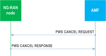
The AMF initiates the procedure by sending a PWS CANCEL REQUEST message to the NG-RAN node.
If the NG-RAN node receives a PWS CANCEL REQUEST message and broadcast of the warning message identified by the Message Identifier and Serial Number IE is ongoing in an area indicated within the Warning Area List IE, the NG-RAN node shall stop broadcasting the warning message within that area and discard the warning message for that area.
If the Warning Area List IE is not included in the PWS CANCEL REQUEST message, the NG-RAN node shall stop broadcasting and discard the warning message identified by the Message Identifier IE and the Serial Number IE in all of the cells in the NG-RAN node.
The NG-RAN node shall acknowledge the PWS CANCEL REQUEST message by sending the PWS CANCEL RESPONSE message, with the Message Identifier IE and the Serial Number IE copied from the PWS CANCEL REQUEST message and shall, if there is an area to report where an ongoing broadcast was stopped successfully, include the Broadcast Cancelled Area List IE.
If an area included in the Warning Area List IE in the PWS CANCEL REQUEST message does not appear in the Broadcast Cancelled Area List IE, the AMF shall consider that the NG-RAN node had no ongoing broadcast to stop for the same Message Identifier and Serial Number in that area.
If the Broadcast Cancelled Area List IE is not included in the PWS CANCEL RESPONSE message, the AMF shall consider that the NG-RAN node had no ongoing broadcast to stop for the same Message Identifier and Serial Number.
If the Cancel-All Warning Messages Indicator IE is present in the PWS CANCEL REQUEST message, then the NG-RAN node shall stop broadcasting and discard all warning messages for the area as indicated in the Warning Area List IE or in all the cells of the NG-RAN node if the Warning Area List IE is not included. The NG-RAN node shall acknowledge the PWS CANCEL REQUEST message by sending the PWS CANCEL RESPONSE message, with the Message Identifier IE and the Serial Number IE copied from the PWS CANCEL REQUEST message and shall, if there is area to report where an ongoing broadcast was stopped successfully, include the Broadcast Cancelled Area List IE with the Number of Broadcasts IE set to 0.
8.9.2.3 Unsuccessful Operation p. 111
Not applicable.
8.9.2.4 Abnormal Conditions p. 111
Void.
8.9.3 PWS Restart Indication p. 111
8.9.3.1 General p. 111
The purpose of the PWS Restart Indication procedure is to inform the AMF that PWS information for some or all cells of the NG-RAN node may be reloaded from the CBC if needed. The procedure uses non UE-associated signalling.
8.9.3.2 Successful Operation p. 111
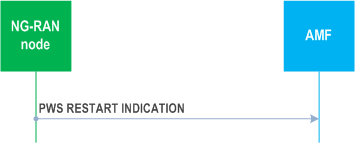
The NG-RAN node initiates the procedure by sending a PWS RESTART INDICATION message to the AMF. On receipt of a PWS RESTART INDICATION message, the AMF shall act as defined in TS 23.527.
If the Emergency Area ID is available, the NG-RAN node shall also include it in the Emergency Area ID List for Restart IE.
8.9.3.3 Abnormal Conditions p. 111
Void.
8.9.4 PWS Failure Indication p. 111
8.9.4.1 General p. 111
The purpose of the PWS Failure Indication procedure is to inform the AMF that ongoing PWS operation for one or more cells of the NG-RAN node has failed. The procedure uses non UE-associated signalling.
8.9.4.2 Successful Operation p. 112
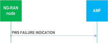
The NG-RAN node initiates the procedure by sending a PWS FAILURE INDICATION message to the AMF. On receipt of a PWS FAILURE INDICATION message, the AMF shall act as defined in TS 23.041.
8.9.4.3 Abnormal Conditions p. 112
Void.