Content for TS 38.413 Word version: 18.2.0
1…
4…
8…
8.2…
8.2.3…
8.3…
8.3.4…
8.4…
8.4.3…
8.5…
8.7…
8.8…
8.10…
8.12…
8.17…
9…
9.2…
9.2.2…
9.2.3…
9.2.4…
9.2.6…
9.2.7…
9.2.9…
9.2.11…
9.2.16…
9.2.17…
9.3…
9.3.1.21…
9.3.1.41…
9.3.1.61…
9.3.1.81…
9.3.1.101…
9.3.1.121…
9.3.1.141…
9.3.1.161…
9.3.1.181…
9.3.1.205…
9.3.1.222…
9.3.1.245…
9.3.2…
9.3.3…
9.3.3.21…
9.3.3.42…
9.3.4…
9.3.4.10…
9.3.5…
9.4…
9.4.4
9.4.5
9.4.6…
9.5…
10…
8.12 Location Reporting Procedures
8.12.1 Location Reporting Control
8.12.2 Location Reporting Failure Indication
8.12.3 Location Report
8.13 UE TNLA Binding Procedures
8.13.1 UE TNLA Binding Release
8.14 UE Radio Capability Management Procedures
8.14.1 UE Radio Capability Info Indication
8.14.2 UE Radio Capability Check
8.14.3 UE Radio Capability ID Mapping
8.15 Data Usage Reporting Procedures
8.15.1 Secondary RAT Data Usage Report
8.16 RIM Information Transfer Procedures
8.16.1 Uplink RIM Information Transfer
8.16.2 Downlink RIM Information Transfer
...
...
8.12 Location Reporting Procedures p. 117
8.12.1 Location Reporting Control p. 117
8.12.1.1 General p. 117
The purpose of the Location Reporting Control procedure is to allow the AMF to request the NG-RAN node to report the UE's current location, or the UE's last known location with time stamp, or the UE's presence in the area of interest while in CM-CONNECTED state as specified in TS 23.501 and TS 23.502. The procedure uses UE-associated signalling.
8.12.1.2 Successful Operation p. 117
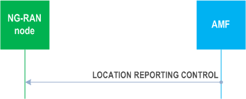
The AMF initiates the procedure by sending a LOCATION REPORTING CONTROL message to the NG-RAN node. On receipt of the LOCATION REPORTING CONTROL message the NG-RAN node shall perform the requested location reporting control action for the UE.
The Location Reporting Request Type IE indicates to the NG-RAN node whether:
- to report directly;
- to report upon change of serving cell;
- to report UE presence in the area of interest;
- to stop reporting at change of serving cell;
- to stop reporting UE presence in the area of interest;
- to cancel location reporting for the UE;
- to report upon change of serving cell and to report UE presence in the area of interest.
8.12.1.3 Abnormal Conditions p. 118
Interactions with Location Reporting Failure Indication procedure:
If the NG-RAN node receives a LOCATION REPORTING CONTROL message containing several Location Reporting Reference ID IE set to the same value, the NG-RAN node shall send the LOCATION REPORTING FAILURE INDICATION message with an appropriate cause value.
If the Location Reporting Request Type IE in the received LOCATION REPORTING CONTROL message contains the Event Type IE set to neither "UE presence in the area of interest" nor "change of serving cell and UE presence in the area of interest", but the Area of Interest List IE is present, the NG-RAN node shall ignore the Area of Interest List IE. and proceed with the Location Reporting Procedure.
8.12.2 Location Reporting Failure Indication p. 118
8.12.2.1 General p. 118
The purpose of the Location Reporting Failure Indication procedure is to allow the NG-RAN node to inform the AMF that the location reporting request contained in the Location Reporting Control procedure, the Handover Resource Allocation procedure or the Initial Context Setup procedure has failed. The procedure uses UE-associated signalling.
8.12.2.2 Successful Operation p. 118
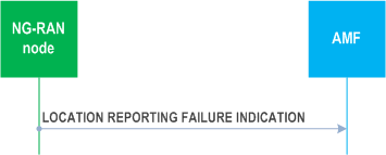
The NG-RAN node initiates the procedure by sending a LOCATION REPORTING FAILURE INDICATION message to the AMF. Upon reception of the LOCATION REPORTING FAILURE INDICATION message the AMF shall, based on the failure reason indicated by the Cause IE, take appropriate action.
8.12.2.3 Abnormal Conditions p. 118
Void.
8.12.3 Location Report p. 119
8.12.3.1 General p. 119
The purpose of the Location Report procedure is to provide the UE's current location, the UE's last known location with time stamp, or the UE's presence in the area of interest to the AMF. The procedure uses UE-associated signalling.
8.12.3.2 Successful Operation p. 119
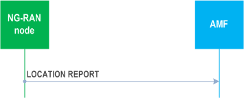
The NG-RAN node initiates the procedure by sending a LOCATION REPORT message to the AMF. The LOCATION REPORT message may be used as a response to the LOCATION REPORTING CONTROL message.
8.12.3.3 Abnormal Conditions p. 119
Void.
8.13 UE TNLA Binding Procedures p. 119
8.13.1 UE TNLA Binding Release p. 119
8.13.1.1 General p. 119
The purpose of the UE TNLA Binding Release procedure is to request the NG-RAN node to release the NGAP UE TNLA binding, while requesting the NG-RAN node to maintain NG-U (user plane connectivity) and UE context information as specified in TS 23.502. The procedure uses UE-associated signalling.
8.13.1.2 Successful Operation p. 119
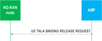
At reception of the UE TNLA BINDING RELEASE REQUEST message, the NG-RAN node shall release the UE TNLA binding for the UE indicated in the UE TNLA BINDING RELEASE REQUEST message. The NG-RAN node shall keep the NG-U (user plane connectivity) and UE context information for the UE, and behave according to TS 23.502.
8.13.1.3 Abnormal Conditions p. 120
Void.
8.14 UE Radio Capability Management Procedures p. 120
8.14.1 UE Radio Capability Info Indication p. 120
8.14.1.1 General p. 120
The purpose of the UE Radio Capability Info Indication procedure is to enable the NG-RAN node to provide to the AMF UE radio capability-related information. The procedure uses UE-associated signalling.
8.14.1.2 Successful Operation p. 120
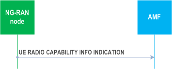
The NG-RAN node controlling a UE-associated logical NG connection initiates the procedure by sending a UE RADIO CAPABILITY INFO INDICATION message to the AMF including the UE radio capability information.
The UE RADIO CAPABILITY INFO INDICATION message may also include paging specific UE radio capability information within the UE Radio Capability for Paging IE. If the UE Radio Capability for Paging IE includes the UE Radio Capability for Paging of NR IE and the UE Radio Capability for Paging of E-UTRA IE, the AMF shall, if supported, use it as specified in TS 23.501.
The UE radio capability information received by the AMF shall replace previously stored corresponding UE radio capability information in the AMF for the UE, as described in TS 23.501.
If the UE RADIO CAPABILITY INFO INDICATION message includes the UE Radio Capability - E-UTRA Format IE, the AMF shall, if supported, use it as specified in TS 23.501.
If the UE RADIO CAPABILITY INFO INDICATION message includes the XR Device with 2Rx IE, the AMF shall, if supported, store this information and use it accordingly.
8.14.1.3 Abnormal Conditions p. 120
Void.
8.14.2 UE Radio Capability Check p. 121
8.14.2.1 General p. 121
The purpose of the UE Radio Capability Check procedure is for the AMF to request the NG-RAN node to derive and provide an indication to the AMF on whether the UE radio capabilities are compatible with the network configuration for IMS voice. The procedure uses UE-associated signalling.
8.14.2.2 Successful Operation p. 121
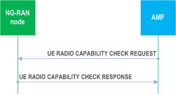
The AMF initiates the procedure by sending a UE RADIO CAPABILITY CHECK REQUEST message. If the UE-associated logical NG-connection is not established, the AMF shall allocate a unique AMF UE NGAP ID to be used for the UE and include the AMF UE NGAP ID IE in the UE RADIO CAPABILITY CHECK REQUEST message; by receiving the AMF UE NGAP ID IE in the UE RADIO CAPABILITY CHECK REQUEST message, the NG-RAN node establishes the UE-associated logical NG-connection.
Upon receipt of the UE RADIO CAPABILITY CHECK REQUEST message, the NG-RAN node checks whether the UE radio capabilities are compatible with the network configuration for IMS voice, and responds with a UE RADIO CAPABILITY CHECK RESPONSE message, as defined in TS 23.502.
If the UE Radio Capability IE is contained in the UE RADIO CAPABILITY CHECK REQUEST message, the NG-RAN node shall use it to determine the value of the IMS Voice Support Indicator IE to be included in the UE RADIO CAPABILITY CHECK RESPONSE message.
If the UE RADIO CAPABILITY CHECK REQUEST message contains the UE Radio Capability ID IE, the NG-RAN node shall, if supported, use it as specified in TS 23.501 and TS 23.502.
8.14.2.3 Unsuccessful Operation p. 121
Not applicable.
8.14.2.4 Abnormal Conditions p. 121
Void.
8.14.3 UE Radio Capability ID Mapping |R16| p. 121
8.14.3.1 General p. 121
The purpose of the UE Radio Capability ID Mapping procedure is for the NG-RAN node to request from the AMF UE Radio Capability information mapped to the UE Radio Capability ID.
The procedure uses non UE-associated signalling.
8.14.3.2 Successful Operation p. 122
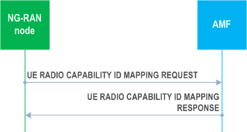
The NG-RAN node initiates the procedure by sending a UE RADIO CAPABILITY ID MAPPING REQUEST message.
Upon receipt of the UE RADIO CAPABILITY ID MAPPING REQUEST message, the AMF shall provide within the UE RADIO CAPABILITY ID MAPPING RESPONSE message the UE Radio Capability information mapped to the UE Capability ID indicated in the UE RADIO CAPABILITY ID MAPPING REQUEST message.
8.14.3.3 Unsuccessful Operation p. 122
Not applicable.
8.14.3.4 Abnormal Conditions p. 122
Void.
8.15 Data Usage Reporting Procedures p. 122
8.15.1 Secondary RAT Data Usage Report p. 122
8.15.1.1 General p. 122
The purpose of the Secondary RAT Data Usage Report procedure is to provide information on the used resources of the secondary RAT (e.g. NR resources during MR-DC operation) as specified in TS 23.501. The procedure uses UE-associated signalling.
8.15.1.2 Successful Operation p. 122
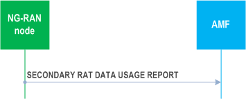
The NG-RAN node initiates the procedure by sending the SECONDARY RAT DATA USAGE REPORT message to the AMF.
If the Handover Flag IE is included in the SECONDARY RAT DATA USAGE REPORT message, it indicates that for each PDU session the AMF should buffer the Secondary RAT Data Usage Report Transfer IE since the secondary RAT data usage report is sent due to handover as defined in TS 23.502.
For each PDU session for which the Secondary RAT Usage Information List IE is included in the Secondary RAT Data Usage Transfer IE, the SMF shall handle this information as specified in TS 23.502.
The NG-RAN node shall, if supported, report in the SECONDARY RAT DATA USAGE REPORT message location information of the UE in the User Location Information IE.
8.15.1.3 Abnormal Conditions p. 123
Void.
8.16 RIM Information Transfer Procedures |R16| p. 123
8.16.1 Uplink RIM Information Transfer p. 123
8.16.1.1 General p. 123
The purpose of the Uplink RIM Information Transfer procedure is to transfer RIM information from the NG-RAN node to the AMF. The AMF does not interpret the transferred RIM information. This procedure uses non-UE associated signalling.
8.16.1.2 Successful Operation p. 123
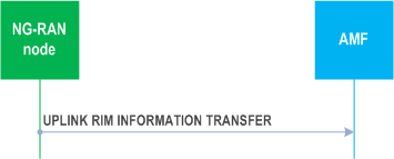
The NG-RAN node initiates the procedure by sending an UPLINK RIM INFORMATION TRANSFER message to the AMF.
Upon reception of the UPLINK RIM INFORMATION TRANSFER message, the AMF shall transparently transfer it towards the NG-RAN node indicated in the Target RAN Node ID IE.
8.16.1.3 Abnormal Conditions p. 123
Void.
8.16.2 Downlink RIM Information Transfer p. 123
8.16.2.1 General p. 123
The purpose of the Downlink RIM Information Transfer procedure is to transfer RIM information from the AMF to the NG-RAN node. This procedure uses non-UE associated signalling.
8.16.2.2 Successful Operation p. 124
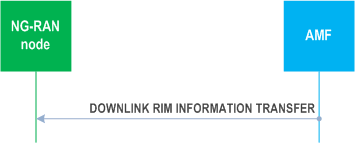
The AMF initiates the procedure by sending a DOWNLINK RIM INFORMATION TRANSFER message to the NG-RAN node. The NG-RAN node may use the RIM information in the received DOWNLINK RIM INFORMATION TRANSFER message for executing the RIM functionality, as specified in TS 38.300.
8.16.2.3 Abnormal Conditions p. 124
Void.