| |
Figure 5.2-1 | NG and Uu user plane |
Figure 5.3-1 | NG and Uu control plane |
Figure 6.1-1 | Overall architecture |
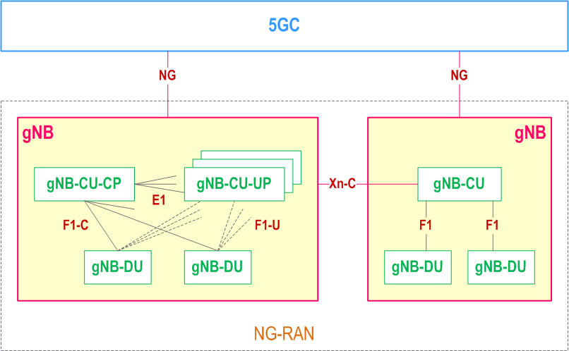
Figure 6.1.2-1 | Overall architecture for separation of gNB-CU-CP and gNB-CU-UP |
Figure 6.1.3-1 | Overall architecture of IAB |
Figure 6.1.4-1 | Protocol stack for F1-U of IAB |
Figure 6.1.4-2 | Protocol stack for F1-C of IAB |
Figure 6.1.4-3 | Protocol stack for IAB F1-C traffic exchanged via the MeNB |
Figure 6.1.4-4 | Protocol stack for IAB F1-C traffic exchanged via the MgNB |
Figure 6.1.4-5 | Protocol stack for IAB F1-C traffic exchanged via the SgNB |
Figure 6.1.6-1 | User plane protocol stack for L2 UE-to-Network Relay |
Figure 6.1.6-2 | Control plane protocol stack for L2 UE-to-Network Relay |
Figure 8.1-1 | UE Initial Access procedure |
Figure 8.2.1.1-1 | Inter-gNB-DU Mobility for intra-NR |
Figure 8.2.1.3-1 | Inter-gNB-DU Conditional Handover or Conditional PSCell Change or subsequent CPAC for intra-NR |
Figure 8.2.1.4-1 | Intra-gNB-DU LTM |
Figure 8.2.1.5-1 | Inter-gNB-DU LTM |
Figure 8.2.1.6-1 | LTM with the change of gNB-CU-UP |
Figure 8.2.2.1-1 | Inter-gNB-DU Mobility using MCG SRB in EN-DC |
Figure 8.2.2.3-1 | Inter-gNB-DU Conditional PSCell Change using MCG SRB without MN negotiation in EN-DC |
Figure 8.2.3.1-1 | IAB intra-CU topology adaptation procedure |
Figure 8.2.3.2-1 | IAB intra-CU topology adaptation procedure using MCG SRB in EN-DC |
Figure 8.2.4-1 | Example for IAB topology with two redundant paths |
Figure 8.2.4-2 | Procedure for establishment of redundant path in IAB topology |
Figure 8.2.5-1 | IAB intra-CU backhaul RLF recovery procedure for an IAB-node in SA mode |
Figure 8.3.1-1 | Procedure for centralized retransmission in intra gNB-CU scenarios |
Figure 8.4.1.1-1 | SgNB addition procedure in EN-DC |
Figure 8.4.2.1-1 | SgNB release procedure in EN-DC (MN initiated) |
Figure 8.4.2.1-2 | SgNB release procedure in EN-DC (SN initiated) |
Figure 8.4.3-1 | SCG Suspend/Resume in RRC_INACTIVE |
Figure 8.4.4.1-1 | SCG Activation or Deactivation in SN Addition procedure |
Figure 8.4.4.2-1 | SCG Activation or Deactivation in MN initiated SN Modification procedure |
Figure 8.4.4.3-1 | SCG Activation or Deactivation in SN initiated SN Modification procedure |
Figure 8.5-1 | F1 startup and cell activation |
Figure 8.6.1-1 | RRC connected to RRC inactive state transition procedure |
Figure 8.6.2-1 | RRC inactive to other RRC states transition procedure |
Figure 8.7-1 | RRC connection reestablishment procedure |
Figure 8.8-1 | Managing multiple TNLAs for F1-C |
Figure 8.9.1-1 | UE Initial Access procedure involving E1 and F1 |
Figure 8.9.2-1 | Bearer context setup over F1-U |
Figure 8.9.3.1-1 | Bearer context release over F1-U - gNB-CU-CP initiated |
Figure 8.9.3.2-1 | Bearer context release over F1-U - gNB-CU-UP initiated |
Figure 8.9.4-1 | Inter-gNB handover involving gNB-CU-UP change |
Figure 8.9.5-1 | Change of gNB-CU-UP |
Figure 8.9.6.1-1 | RRC Connected to RRC Inactive state transition |
Figure 8.9.6.2-1 | RRC Inactive to RRC Connected state transition |
Figure 8.9.7-1 | Trace activation/deactivation over F1 and E1 |
Figure 8.9.8-1 | Signalling flow for IAB BH RLC channel establishment procedure |
Figure 8.10-1 | Managing multiple TNLAs for E1 |
Figure 8.11.2-1 | UE Initial Access procedure and network sharing with multiple cell-ID broadcast |
Figure 8.11.3-1 | RRC Connection Reestablishment and network sharing with multiple cell-ID broadcast |
Figure 8.12.1-1 | The integration procedure for IAB-node in SA |
Figure 8.12.2-1 | Signalling flow for IAB integration procedure in NSA |
Figure 8.12.3-1 | Decoupled mobile IAB-node integration procedure |
Figure 8.13.1-1 | Signalling based MDT Activation |
Figure 8.13.2.2-1 | Management based MDT Activation in gNB-CU-CP |
Figure 8.13.2.3-1 | Management based MDT Activation in gNB-DU |
Figure 8.13.2.4-1 | Management based MDT Activation in gNB-CU-UP |
Figure 8.13.2.5-1 | User consent propagation in EN-DC |
Figure 8.13.2.6-1 | User consent propagation in NR-DC and NGEN-DC |
Figure 8.13.2.7-1 | Data anonymization in MR-DC when the SN is the SgNB |
Figure 8.14.1.1-1 | Example of signalling of RLF information from gNB-CU to gNB-DU in NG RAN |
Figure 8.14.1.2-1 | Example of signalling of RACH information from gNB-CU to gNB-DU in NG-RAN |
Figure 8.15.1.1-1 | Broadcast MBS Session Setup |
Figure 8.15.1.1a-1 | Broadcast MBS Session Setup for resource efficiency for MOCN |
Figure 8.15.1.1b-1 | Broadcast MBS Session Setup for RAN sharing with multiple cell-ID broadcast |
Figure 8.15.1.2-1 | Multicast MBS Session Context establishment |
Figure 8.15.1.3-1 | Multicast MRB type re-configuration with F1-U ptp retransmission tunnel establishment |
Figure 8.15.2.1-1 | Inter-gNB-CU Mobility for Multicast |
Figure 8.16.1-1 | Conditional Secondary Node Addition procedure |
Figure 8.17.2.1-1 | IAB inter-CU topology redundancy procedure |
Figure 8.17.3.1-1 | IAB inter-CU topology adaptation procedure |
Figure 8.17.3.2-1 | IAB inter-CU topology adaptation procedure with descendant IAB-node |
Figure 8.17.4-1 | IAB inter-CU backhaul RLF recovery procedure for an IAB-node in SA mode |
Figure 8.18.1-1 | RACH based Small Data Transmission in RRC Inactive state |
Figure 8.18.2-1 | CG based Small Data Transmission in RRC Inactive state |
Figure 8.18.3-1 | RA-SDT or non-SDT with CG-SDT configuration |
Figure 8.18.4-1 | Mobile Terminated Small Data Transmission in RRC Inactive state |
Figure 8.19.1-1 | Remote UE Initial Access procedure |
Figure 8.19.2-1 | Remote UE RRC Reestablishment procedure |
Figure 8.19.3-1 | Remote UE RRC Resume procedure |
Figure 8.19.4.1-1 | U2N Remote UE Direct-to-indirect Path Switch with gNB-DU change procedure |
Figure 8.19.4.2-1 | U2N Remote UE Direct-to-indirect Path Switch without gNB-DU change procedure |
Figure 8.19.4.3-1 | U2N Remote UE Direct-to-indirect Path Switch with gNB-CU change procedure |
Figure 8.21.1-1 | The integration procedure for Network Controlled Repeater |
Figure 8.22.1-1 | Signalling procedure of inter-DU direct path addition on top of indirect path |
Figure 8.22.2-1 | Signalling procedure of inter-DU indirect path addition on top of direct path |
Figure 8.22.3-1 | Signalling procedure of intra-DU direct path addition on top of indirect path |
Figure 8.22.4-1 | Signalling procedure of intra-DU indirect path addition on top of direct path |
Figure 8.23.1-1 | Procedure for Xn-based migration of mobile IAB-MT |
Figure 8.23.2-1 | Procedure for NG-based migration of mobile IAB-MT |
Figure 8.23.3-1 | Mobile IAB-DU inter-CU migration procedure |
Figure 8.23.4-1 | Procedure for RLF recovery of mobile IAB-node |
Figure 8.24.1-1 | RAN TSS reporting towards the CN |
Figure 8.24.2-1 | RAN TSS reporting towards the UE in RRC_CONNECTED state |
Figure 11.1-1 | Managing multiple TNLAs for Xn-C |
Figure A-1 | Example deployment of an Logical gNB/en-gNB |