Content for TS 38.300 Word version: 18.2.0
1…
4…
4.7…
5…
5.3…
5.4…
6…
6.2…
6.6…
7…
8…
9…
9.2.2…
9.2.2.5…
9.2.3…
9.2.3.2…
9.2.3.3…
9.2.4…
9.2.6…
9.3…
10…
11…
15…
15.5…
16…
16.2…
16.3…
16.4…
16.8…
16.9…
16.10…
16.12…
16.12.5…
16.12.6…
16.12.6.3
16.12.7
16.13…
16.14…
16.15…
16.18…
16.19…
16.21…
16.21.3…
17…
18…
19
20…
21…
A…
B…
C…
G…
11 UE Power Saving
12 QoS
12.1 Overview
12.2 Explicit Congestion Notification
13 Security
13.1 Overview and Principles
13.2 Security Termination Points
13.3 State Transitions and Mobility
14 UE Capabilities
...
...
11 UE Power Saving p. 125
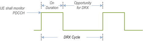
The PDCCH monitoring activity of the UE in RRC connected mode is governed by DRX, BA, DCP and cell DTX (see clause 15.4.2.3).
When DRX is configured, the UE does not have to continuously monitor PDCCH. DRX is characterized by the following:
- on-duration: duration that the UE waits for, after waking up, to receive PDCCHs. If the UE successfully decodes a PDCCH, the UE stays awake and starts the inactivity timer;
- inactivity-timer: duration that the UE waits to successfully decode a PDCCH, from the last successful decoding of a PDCCH, failing which it can go back to sleep. The UE shall restart the inactivity timer following a single successful decoding of a PDCCH for a first transmission only (i.e. not for retransmissions);
- retransmission-timer: duration until a retransmission can be expected;
- cycle: specifies the periodic repetition of the on-duration followed by a possible period of inactivity (see Figure 11-1 below);
- active-time: total duration that the UE monitors PDCCH. This includes the "on-duration" of the DRX cycle, the time UE is performing continuous reception while the inactivity timer has not expired, and the time when the UE is performing continuous reception while waiting for a retransmission opportunity.
A SL UE can be configured with DRX, in which case, PDCCH providing SL grants can be send to the UE only during its active time.
When BA is configured, the UE only has to monitor PDCCH on the one active BWP i.e. it does not have to monitor PDCCH on the entire DL frequency of the cell. A BWP inactivity timer (independent from the DRX inactivity-timer described above) is used to switch the active BWP to the default one: the timer is restarted upon successful PDCCH decoding and the switch to the default BWP takes place when it expires.
In addition, the UE may be indicated, when configured accordingly, whether it is required to monitor or not the PDCCH during the next occurrence of the on-duration by a DCP monitored on the active BWP. If the UE does not detect a DCP on the active BWP, it does not monitor the PDCCH during the next occurrence of the on-duration, unless it is explicitly configured to do so in that case.
A UE can only be configured to monitor DCP when connected mode DRX is configured, and at occasion(s) at a configured offset before the on-duration. More than one monitoring occasion can be configured before the on-duration. The UE does not monitor DCP on occasions occurring during active-time, measurement gaps, BWP switching, or when it monitors response for a CFRA preamble transmission for beam failure recovery (see clause 9.2.6), in which case it monitors the PDCCH during the next on-duration. If no DCP is configured in the active BWP, UE follows normal DRX operation.
When CA is configured, DCP is only configured on the PCell.
One DCP can be configured to control PDCCH monitoring during on-duration for one or more UEs independently.
Power saving in RRC_IDLE and RRC_INACTIVE can also be achieved by UE relaxing neighbour cells RRM measurements when it meets the criteria determining it is in low mobility and/or not at cell edge. When UE is configured with both high speed measurements and RRM measurement relaxation as specified in TS 38.331, it is up to UE implementation whether to apply the FR1 high speed RRM requirements or the relaxed RRM requirements when the low mobility related criterion is configured and fulfilled as specified in TS 38.133.
UE power saving may be enabled by adapting the DL maximum number of MIMO layers by BWP switching.
Power saving is also enabled during active-time via cross-slot scheduling, which facilitates UE to achieve power saving with the assumption that it won't be scheduled to receive PDSCH, triggered to receive A-CSI or transmit a PUSCH scheduled by the PDCCH until the minimum scheduling offsets K0 and K2. Dynamic adaptation of the minimum scheduling offsets K0 and K2 is controlled by PDCCH.
Serving Cells of a MAC entity may be configured by RRC in two DRX groups with separate DRX parameters. When RRC does not configure a secondary DRX group, there is only one DRX group and all Serving Cells belong to that one DRX group. When two DRX groups are configured, each Serving Cell is uniquely assigned to either of the two groups. The DRX parameters that are separately configured for each DRX group are on-duration and inactivity-timer.
UE power saving in RRC_IDLE/RRC_INACTIVE may be achieved by providing the configuration for TRS with CSI-RS for tracking in TRS occasions. The TRS in TRS occasions may allow UEs in RRC_IDLE/RRC_INACTIVE to sleep longer before waking-up for its paging occasion. The TRS occasions configuration is provided in either SIB17 or SIB17bis. The availability of TRS in the TRS occasions is indicated by L1 availability indication. These TRSs may also be used by the UEs configured with eDRX.
UE power saving may be achieved by UE relaxing measurements for RLM/BFD. When configured, UE determines whether it is in low mobility state and/or whether its serving cell radio link quality is better than a threshold. The configuration for low mobility and good serving cell quality criterion is provided through dedicated RRC signalling.
RLM and BFD relaxation may be enabled/disabled separately through RRC Configuration. Additionally, RLM relaxation may be enabled/disabled on per Cell Group basis while BFD relaxation may be enabled/disabled on per serving cell basis.
The UE is only allowed to perform RLM and/or BFD relaxation when relaxed measurement criterion for low mobility and/or for good serving cell quality is met. If configured to do so, the UE shall trigger reporting of its RLM and/or BFD relaxation status through UE assistance information if the UE changes its respective RLM and/or BFD relaxation status while meeting the UE minimum requirements specified in TS 38.133.
UE power saving may also be achieved through PDCCH monitoring adaptation mechanisms when configured by the network, including skipping of PDCCH monitoring and Search space set group (SSSG) switching. In this case UE does not monitor PDCCH during the PDCCH skipping duration except for the cases as specified in TS 38.213, or monitors PDCCH according to the search space sets applied in SSSG.
12 QoS p. 126
12.1 Overview p. 126
The 5G QoS model is based on QoS Flows (see TS 23.501) and supports both QoS Flows that require guaranteed flow bit rate (GBR QoS Flows) and QoS Flows that do not require guaranteed flow bit rate (non-GBR QoS Flows). At NAS level (see TS 23.501), the QoS flow is thus the finest granularity of QoS differentiation in a PDU session. A QoS flow is identified within a PDU session by a QoS Flow ID (QFI) carried in an encapsulation header over NG-U.
The QoS architecture in NG-RAN, both for NR connected to 5GC and for E-UTRA connected to 5GC, is depicted in the Figure 12-1 and described in the following:
- For each UE, 5GC establishes one or more PDU Sessions;
- Except for NB-IoT, IAB-MT in SA mode, and NCR-MT, for each UE, the NG-RAN establishes at least one Data Radio Bearers (DRB) together with the PDU Session and additional DRB(s) for QoS flow(s) of that PDU session can be subsequently configured (it is up to NG-RAN when to do so);
- If NB-IoT UE supports NG-U data transfer, the NG-RAN may establish Data Radio Bearers (DRB) together with the PDU Session and one PDU session maps to only one DRB;
- The NG-RAN maps packets belonging to different PDU sessions to different DRBs;
- NAS level packet filters in the UE and in the 5GC associate UL and DL packets with QoS Flows;
- AS-level mapping rules in the UE and in the NG-RAN associate UL and DL QoS Flows with DRBs.
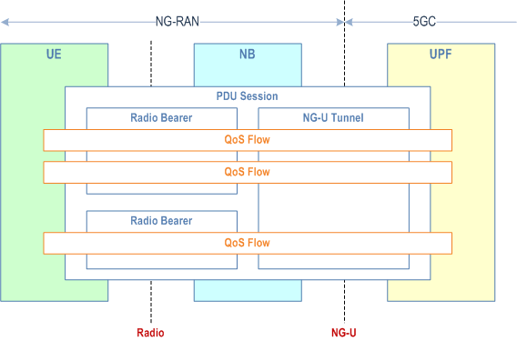
NG-RAN and 5GC ensure quality of service (e.g. reliability and target delay) by mapping packets to appropriate QoS Flows and DRBs. Hence there is a 2-step mapping of IP-flows to QoS flows (NAS) and from QoS flows to DRBs (Access Stratum).
At NAS level, a QoS flow is characterised by a QoS profile provided by 5GC to NG-RAN and QoS rule(s) provided by 5GC to the UE. The QoS profile is used by NG-RAN to determine the treatment on the radio interface while the QoS rules dictates the mapping between uplink User Plane traffic and QoS flows to the UE. A QoS flow may either be GBR or Non-GBR depending on its profile. The QoS profile of a QoS flow contains QoS parameters, for instance (see TS 23.501):
-
For each QoS flow:
- A 5G QoS Identifier (5QI);
- An Allocation and Retention Priority (ARP).
-
In case of a GBR QoS flow only:
- Guaranteed Flow Bit Rate (GFBR) for both uplink and downlink;
- Maximum Flow Bit Rate (MFBR) for both uplink and downlink;
- Maximum Packet Loss Rate for both uplink and downlink;
- Delay Critical Resource Type;
- Notification Control.
-
In case of Non-GBR QoS only:
- Reflective QoS Attribute (RQA): the RQA, when included, indicates that some (not necessarily all) traffic carried on this QoS flow is subject to reflective quality of service (RQoS) at NAS;
- Additional QoS Flow Information.
- Priority level;
- Packet Delay Budget (including Core Network Packet Delay Budget);
- Packet Error Rate;
- Averaging window;
- Maximum Data Burst Volume.
- Reflective mapping: for each DRB, the UE monitors the QFI(s) of the downlink packets and applies the same mapping in the uplink; that is, for a DRB, the UE maps the uplink packets belonging to the QoS flows(s) corresponding to the QFI(s) and PDU Session observed in the downlink packets for that DRB. To enable this reflective mapping, the NG-RAN marks downlink packets over Uu with QFI.
- Explicit Configuration: QoS flow to DRB mapping rules can be explicitly signalled by RRC.
12.2 Explicit Congestion Notification p. 129
The gNB and the UE support of the Explicit Congestion Notification (ECN) is specified in Section 5 of RFC 3168.
13 Security p. 129
13.1 Overview and Principles p. 129
The following principles apply to NR connected to 5GC security, see TS 33.501:
- For user data (DRBs), ciphering provides user data confidentiality and integrity protection provides user data integrity;
- For RRC signalling (SRBs), ciphering provides signalling data confidentiality and integrity protection signalling data integrity;
- For key management and data handling, any entity processing cleartext shall be protected from physical attacks and located in a secure environment;
- The gNB (AS) keys are cryptographically separated from the 5GC (NAS) keys;
- Separate AS and NAS level Security Mode Command (SMC) procedures are used;
- A sequence number (COUNT) is used as input to the ciphering and integrity protection and a given sequence number must only be used once for a given key (except for identical re-transmission) on the same radio bearer in the same direction.
-
Key for AMF:
- KAMF is a key derived by ME and SEAF from KSEAF.
-
Keys for NAS signalling:
- KNASint is a key derived by ME and AMF from KAMF, which shall only be used for the protection of NAS signalling with a particular integrity algorithm;
- KNASenc is a key derived by ME and AMF from KAMF, which shall only be used for the protection of NAS signalling with a particular encryption algorithm.
-
Key for gNB:
- KgNB is a key derived by ME and AMF from KAMF. KgNB is further derived by ME and source gNB when performing horizontal or vertical key derivation.
-
Keys for UP traffic:
- KUPenc is a key derived by ME and gNB from KgNB, which shall only be used for the protection of UP traffic between ME and gNB with a particular encryption algorithm;
- KUPint is a key derived by ME and gNB from KgNB, which shall only be used for the protection of UP traffic between ME and gNB with a particular integrity algorithm.
-
Keys for RRC signalling:
- KRRCint is a key derived by ME and gNB from KgNB, which shall only be used for the protection of RRC signalling with a particular integrity algorithm;
- KRRCenc is a key derived by ME and gNB from KgNB, which shall only be used for the protection of RRC signalling with a particular encryption algorithm.
-
Intermediate keys:
- NH is a key derived by ME and AMF to provide forward security.
- KgNB* is a key derived by ME and gNB when performing a horizontal or vertical key derivation.
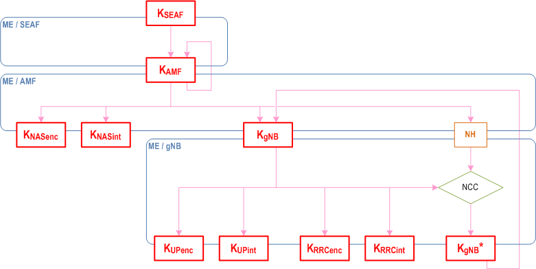
With such key derivation, a gNB with knowledge of a KgNB, shared with a UE, is unable to compute any previous KgNB that has been used between the same UE and a previous gNB, therefore providing backward security. Similarly, a gNB with knowledge of a KgNB, shared with a UE, is unable to predict any future KgNB that will be used between the same UE and another gNB after n or more handovers (since NH parameters are only computable by the UE and the AMF).
The AS SMC procedure is for RRC and UP security algorithms negotiation and RRC security activation. When AS security context is to be established in the gNB, the AMF sends the complete UE 5G security capabilities to the gNB (i.e., all bits for every capability defined in TS 24.501 and received in NAS signalling). At handover (or at UE Context retrieval), the complete UE 5G security capabilities are also sent by the source gNB to the target gNB (or by the last serving gNB to the receiving gNB respectively). The gNB chooses the ciphering algorithm which has the highest priority from its configured list and is also present in the UE 5G security capabilities. The gNB also chooses the integrity algorithm which has the highest priority from its configured list and is also present in the UE 5G security capabilities. The chosen algorithms are indicated to the UE in the AS SMC and this message is integrity protected. RRC downlink ciphering (encryption) at the gNB starts after sending the AS SMC message. RRC uplink deciphering (decryption) at the gNB starts after receiving and successful verification of the integrity protected AS security mode complete message from the UE. The UE verifies the validity of the AS SMC message from the gNB by verifying the integrity of the received message. RRC uplink ciphering (encryption) at the UE starts after sending the AS security mode complete message. RRC downlink deciphering (decryption) at the UE shall start after receiving and successful verification of the AS SMC message. The RRC Connection Reconfiguration procedure used to add DRBs shall be performed only after RRC security has been activated as part of the AS SMC procedure.
A UE connected to 5GC, shall support integrity protected DRBs at any data rate, up to and including the highest data rate supported by the UE for both UL and DL. In case of failed integrity check (i.e. faulty or missing MAC-I), the concerned PDU shall be discarded by the receiving PDCP entity.
Key refresh is possible for KgNB, KRRCenc, KRRCint, KUPenc, and KUPint and can be initiated by the gNB when a PDCP COUNTs are about to be re-used with the same Radio Bearer identity and with the same KgNB. Key re-keying is also possible for the KgNB, KRRCenc, KRRCint, KUPenc, and KUPint and can be initiated by the AMF when a 5G AS security context different from the currently active one shall be activated.
13.2 Security Termination Points p. 131
The Table below describes the security termination points.
| Ciphering | Integrity Protection | |
|---|---|---|
| NAS Signalling | AMF | AMF |
| RRC Signalling | gNB | gNB |
| User Plane Data | gNB | gNB |
13.3 State Transitions and Mobility p. 131
As a general principle, on RRC_IDLE to RRC_CONNECTED transitions, RRC protection keys and UP protection keys are generated while keys for NAS protection as well as higher layer keys are assumed to be already available. These higher layer keys may have been established as a result of an AKA run, or as a result of a transfer from another AMF during handover or idle mode mobility see TS 23.502).
On RRC_CONNECTED to RRC_IDLE transitions, the gNBs deletes the keys it stores for that UE such that state information for idle mode UEs only has to be maintained in AMF. It is also assumed that gNB does no longer store state information about the corresponding UE and deletes the current keys from its memory. In particular, on connected to idle transitions:
- The gNB and UE delete NH, KgNB, KRRCint, KRRCenc, KUPint and KUPenc and related NCC;
- AMF and UE keeps KAMF, KNASint and KNASenc stored.
14 UE Capabilities p. 132
The UE capabilities in NR rely on a hierarchical structure where each capability parameter is defined per UE, per duplex mode (FDD/TDD), per frequency range (FR1/FR2), per band, per band combinations, … as the UE may support different functionalities depending on those (see TS 38.306).
The UE capabilities in NR do not rely on UE categories: UE categories associated to fixed peak data rates are only defined for marketing purposes and not signalled to the network. Instead, the peak data rate for a given set of aggregated carriers in a band or band combination is the sum of the peak data rates of each individual carrier in that band or band combination, where the peak data rate of each individual carrier is computed according to the capabilities supported for that carrier in the corresponding band or band combination.
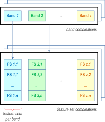
For each block of contiguous serving cells in a band, the set of features supported thereon is defined in a Feature Set (FS). The UE may indicate several Feature Sets for a band (also known as feature sets per band) to advertise different alternative features for the associated block of contiguous serving cells in that band. The two-dimensional matrix of feature sets for all the bands of a band combination (i.e. all the feature sets per band) is referred to as a feature set combination. In a feature set combination, the number of feature sets per band is equal to the number of band entries in the corresponding band combination, and all feature sets per band have the same number of feature sets. Each band combination is linked to one feature set combination. This is depicted on Figure 14-1 below:
In addition, for some features in intra-band contiguous CA, the UE reports its capabilities individually per carrier. Those capability parameters are sent in feature set per component carrier and they are signalled in the corresponding FSs (per Band) i.e. for the corresponding block of contiguous serving cells in a band. The capability applied to each individual carrier in a block is agnostic to the order in which they are signalled in the corresponding FS.
To limit signalling overhead, the gNB can request the UE to provide NR capabilities for a restricted set of bands. When responding, the UE can skip a subset of the requested band combinations according to the UE capability fallback behaviour as specified in TS 38.306 and in TS 38.331. An eRedCap UE may ignore UE capability filtering and send all supported bands in the mirrored UE capability filter with an explicit indication on whether the filter was ignored or not.
If supported by the UE and the network, the UE may provide an ID in NAS signalling that represents its radio capabilities for one or more RATs in order to reduce signalling overhead. The ID may be assigned either by the manufacturer or by the serving PLMN. The manufacturer-assigned ID corresponds to a pre-provisioned set of capabilities. In the case of the PLMN-assigned ID, assignment takes place in NAS signalling.
The AMF stores the UE Radio Capability uploaded by the gNB as specified in TS 23.501.
The gNB can request the UE capabilities for RAT-Types NR, EUTRA, UTRA-FDD. The UTRAN capabilities, i.e. the INTER RAT HANDOVER INFO, include START-CS, START-PS and "predefined configurations", which are "dynamic" IEs. In order to avoid the START values desynchronisation and the key replaying issue, the gNB always requests the UE UTRA-FDD capabilities before handover to UTRA-FDD. The gNB does not upload the UE UTRA-FDD capabilities to the AMF.
![]()
![]()
![]()