Content for TS 38.300 Word version: 18.2.0
1…
4…
4.7…
5…
5.3…
5.4…
6…
6.2…
6.6…
7…
8…
9…
9.2.2…
9.2.2.5…
9.2.3…
9.2.3.2…
9.2.3.3…
9.2.4…
9.2.6…
9.3…
10…
11…
15…
15.5…
16…
16.2…
16.3…
16.4…
16.8…
16.9…
16.10…
16.12…
16.12.5…
16.12.6…
16.12.6.3
16.12.7
16.13…
16.14…
16.15…
16.18…
16.19…
16.21…
16.21.3…
17…
18…
19
20…
21…
A…
B…
C…
G…
4 Overall Architecture and Functional Split
4.1 Overall Architecture
4.2 Functional Split
4.3 Network Interfaces
4.3.1 NG Interface
4.3.1.1 NG User Plane
4.3.1.2 NG Control Plane
4.3.2 Xn Interface
4.3.2.1 Xn User Plane
4.3.2.2 Xn Control Plane
4.4 Radio Protocol Architecture
4.4.1 User Plane
4.4.2 Control Plane
4.5 Multi-Radio Dual Connectivity
4.6 Radio Access Network Sharing
...
...
4 Overall Architecture and Functional Split p. 24
4.1 Overall Architecture p. 24
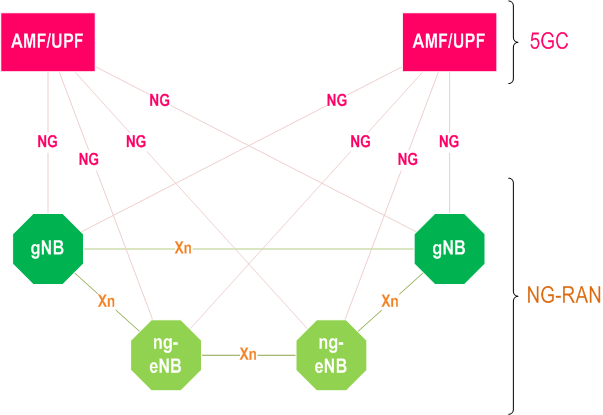
An NG-RAN node is either:
- a gNB, providing NR user plane and control plane protocol terminations towards the UE; or
- an ng-eNB, providing E-UTRA user plane and control plane protocol terminations towards the UE.
4.2 Functional Split p. 25
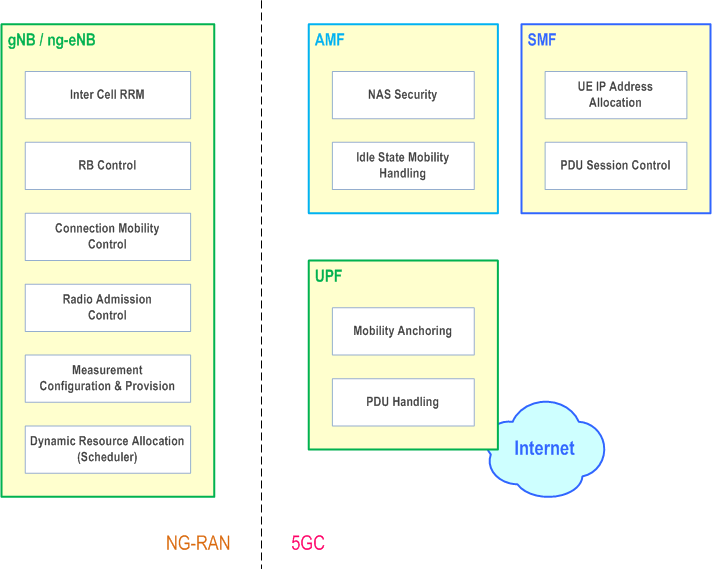
The gNB and ng-eNB host the following functions:
- Functions for Radio Resource Management: Radio Bearer Control, Radio Admission Control, Connection Mobility Control, Dynamic allocation of resources to UEs in uplink, downlink and sidelink (scheduling);
- IP and Ethernet header compression, uplink data decompression, encryption and integrity protection of data;
- Selection of an AMF at UE attachment when no routing to an AMF can be determined from the information provided by the UE;
- Routing of User Plane data towards UPF(s);
- Routing of Control Plane information towards AMF;
- Connection setup and release;
- Scheduling and transmission of paging messages;
- Scheduling and transmission of system broadcast information (originated from the AMF or OAM);
- Measurement and measurement reporting configuration for mobility and scheduling;
- Transport level packet marking in the uplink;
- Session Management;
- Support of Network Slicing;
- QoS Flow management and mapping to data radio bearers;
- Support of UEs in RRC_INACTIVE state;
- Distribution function for NAS messages;
- Radio access network sharing;
- Dual Connectivity;
- Tight interworking between NR and E-UTRA;
- Maintain security and radio configuration for User Plane CIoT 5GS Optimisation, as defined in TS 23.501 (ng-eNB only).
- NAS signalling termination;
- NAS signalling security;
- AS Security control;
- Inter CN node signalling for mobility between 3GPP access networks;
- Idle mode UE Reachability (including control and execution of paging retransmission);
- Registration Area management;
- Support of intra-system and inter-system mobility;
- Access Authentication;
- Access Authorization including check of roaming rights;
- Mobility management control (subscription and policies);
- Support of Network Slicing;
- SMF selection.
- Selection of CIoT 5GS optimisations;
- Anchor point for Intra-/Inter-RAT mobility (when applicable);
- External PDU session point of interconnect to Data Network;
- Packet routing & forwarding;
- Packet inspection and User plane part of Policy rule enforcement;
- Traffic usage reporting;
- Uplink classifier to support routing traffic flows to a data network;
- Branching point to support multi-homed PDU session;
- QoS handling for user plane, e.g. packet filtering, gating, UL/DL rate enforcement;
- Uplink Traffic verification (SDF to QoS flow mapping);
- Downlink packet buffering and downlink data notification triggering.
- Session Management;
- UE IP address allocation and management;
- Selection and control of UP function;
- Configures traffic steering at UPF to route traffic to proper destination;
- Control part of policy enforcement and QoS;
- Downlink Data Notification.
4.3 Network Interfaces p. 27
4.3.1 NG Interface p. 27
4.3.1.1 NG User Plane p. 27
The NG user plane interface (NG-U) is defined between the NG-RAN node and the UPF. The user plane protocol stack of the NG interface is shown on Figure 4.3.1.1-1. The transport network layer is built on IP transport and GTP-U is used on top of UDP/IP to carry the user plane PDUs between the NG-RAN node and the UPF.
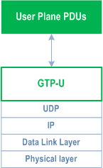
NG-U provides non-guaranteed delivery of user plane PDUs between the NG-RAN node and the UPF.
Further details of NG-U can be found in TS 38.410.
4.3.1.2 NG Control Plane p. 27
The NG control plane interface (NG-C) is defined between the NG-RAN node and the AMF. The control plane protocol stack of the NG interface is shown on Figure 4.3.1.2-1. The transport network layer is built on IP transport. For the reliable transport of signalling messages, SCTP is added on top of IP. The application layer signalling protocol is referred to as NGAP (NG Application Protocol). The SCTP layer provides guaranteed delivery of application layer messages. In the transport, IP layer point-to-point transmission is used to deliver the signalling PDUs.
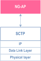
NG-C provides the following functions:
- NG interface management;
- UE context management;
- UE mobility management;
- Transport of NAS messages;
- Paging;
- PDU Session Management;
- Configuration Transfer;
- Warning Message Transmission.
4.3.2 Xn Interface p. 28
4.3.2.1 Xn User Plane p. 28
The Xn User plane (Xn-U) interface is defined between two NG-RAN nodes. The user plane protocol stack on the Xn interface is shown in Figure 4.3.2.1-1. The transport network layer is built on IP transport and GTP-U is used on top of UDP/IP to carry the user plane PDUs.
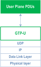
Xn-U provides non-guaranteed delivery of user plane PDUs and supports the following functions:
- Data forwarding;
- Flow control.
4.3.2.2 Xn Control Plane p. 29
The Xn control plane interface (Xn-C) is defined between two NG-RAN nodes. The control plane protocol stack of the Xn interface is shown on Figure 4.3.2.2-1. The transport network layer is built on SCTP on top of IP. The application layer signalling protocol is referred to as XnAP (Xn Application Protocol). The SCTP layer provides the guaranteed delivery of application layer messages. In the transport IP layer point-to-point transmission is used to deliver the signalling PDUs.
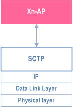
The Xn-C interface supports the following functions:
- Xn interface management;
- UE mobility management, including context transfer and RAN paging;
- Dual connectivity.
4.4 Radio Protocol Architecture p. 29
4.4.1 User Plane p. 29
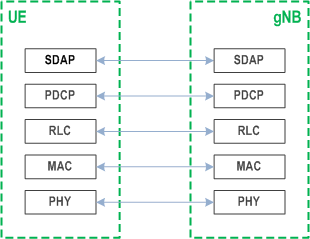
The Figure below shows the protocol stack for the user plane, where SDAP, PDCP, RLC and MAC sublayers (terminated in gNB on the network side) perform the functions listed in clause 6.
4.4.2 Control Plane p. 30
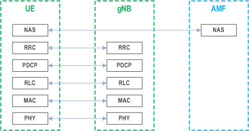
The Figure below shows the protocol stack for the control plane, where:
- PDCP, RLC and MAC sublayers (terminated in gNB on the network side) perform the functions listed in clause 6;
- RRC (terminated in gNB on the network side) performs the functions listed in clause 7;
- NAS control protocol (terminated in AMF on the network side) performs the functions listed in TS 23.501), for instance: authentication, mobility management, security control…
4.5 Multi-Radio Dual Connectivity p. 30
NG-RAN supports Multi-Radio Dual Connectivity (MR-DC) operation whereby a UE in RRC_CONNECTED is configured to utilise radio resources provided by two distinct schedulers, located in two different NG-RAN nodes connected via a non-ideal backhaul, one providing NR access and the other one providing either E-UTRA or NR access. Further details of MR-DC operation, including Conditional PSCell Addition (CPA) and Conditional PSCell Change (CPC), can be found in TS 37.340.
4.6 Radio Access Network Sharing p. 30
NG-RAN supports radio access network sharing as defined in TS 23.501.
If NR access is shared, system information broadcast in a shared cell indicates a TAC and a Cell Identity for each subset of PLMNs, PNI-NPNs and SNPNs. NR access provides only one TAC and one Cell Identity per cell per PLMN, SNPN or PNI-NPN. In this version of the specification, a Cell Identity can only belong to one network type among PLMN, PNI-NPN or SNPN as defined in TS 23.501.
Each Cell Identity associated with a subset of PLMNs, SNPNs or PNI-NPNs identifies its serving NG-RAN node.