Content for TS 38.300 Word version: 18.3.0
1…
4…
4.7…
5…
5.3…
5.4…
6…
6.2…
6.6…
7…
8…
9…
9.2.2…
9.2.2.5…
9.2.3…
9.2.3.2…
9.2.3.3…
9.2.4…
9.2.6…
9.3…
10…
11…
15…
15.5…
16…
16.2…
16.3…
16.4…
16.8…
16.9…
16.10…
16.12…
16.12.5…
16.12.6…
16.12.6.3
16.12.7
16.13…
16.14…
16.15…
16.18…
16.19…
16.21…
16.21.3…
17…
18…
19
20…
21…
A…
B…
C…
G…
B Deployment Scenarios
B.1 Supplementary Uplink
B.2 Multiple SSBs in a carrier
B.3 NR Operation with Shared Spectrum
B.4 Example implementation of Non-Terrestrial Networks
...
...
B Deployment Scenarios p. 251
B.1 Supplementary Uplink p. 251
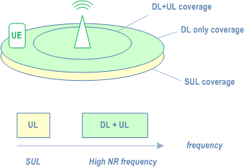
To improve UL coverage for high frequency scenarios, SUL can be configured (see TS 38.101-1). With SUL, the UE is configured with 2 ULs for one DL of the same cell as depicted on Figure B.1-1 below:

B.2 Multiple SSBs in a carrier p. 251
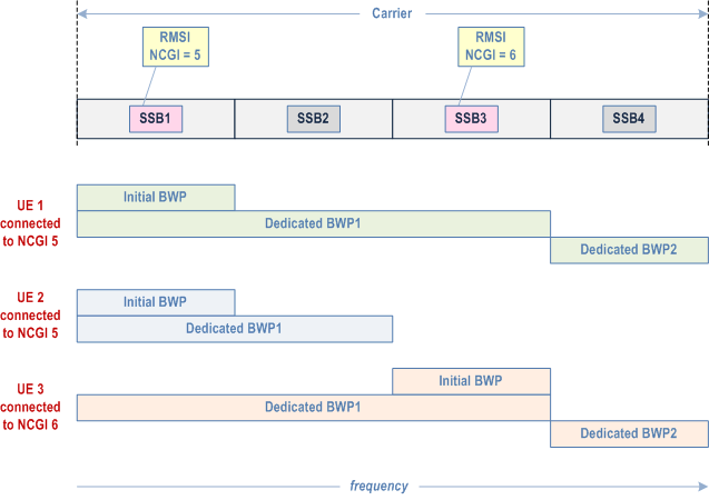
For a UE in RRC_CONNECTED, the BWPs configured by a serving cell may overlap in the frequency domain with the BWPs configured for other UEs by other cells within a carrier. Multiple SSBs may also be transmitted within the frequency span of a carrier used by the serving cell. However, from the UE perspective, each serving cell is associated to at most a single SSB. Figure B.2-1 below describes a scenario with multiple SSBs in a carrier, identifying two different cells (NCGI = 5, associated to SSB1, and NCGI = 6, associated to SSB3) with overlapping BWPs, and where RRM measurements can be configured to be performed by the UE on each of the available SSBs, i.e. SSB1, SSB2, SSB3 and SSB4.

B.3 NR Operation with Shared Spectrum |R16| p. 252
NR Radio Access operating with shared spectrum channel access can support the following deployment scenarios:
- Scenario A: Carrier aggregation between NR in licensed spectrum (SpCell) and NR in shared spectrum (SCell);
-
Scenario B: Dual connectivity between LTE in licensed spectrum and NR in shared spectrum (PSCell);
- Scenario A.1: SCell is not configured with uplink (DL only);
- Scenario A.2: SCell is configured with uplink (DL+UL).
- Scenario C: NR in shared spectrum (PCell);
- Scenario D: NR cell in shared spectrum and uplink in licensed spectrum;
- Scenario E: Dual connectivity between NR in licensed spectrum (PCell) and NR in shared spectrum (PSCell).
B.4 Example implementation of Non-Terrestrial Networks |R17| p. 252
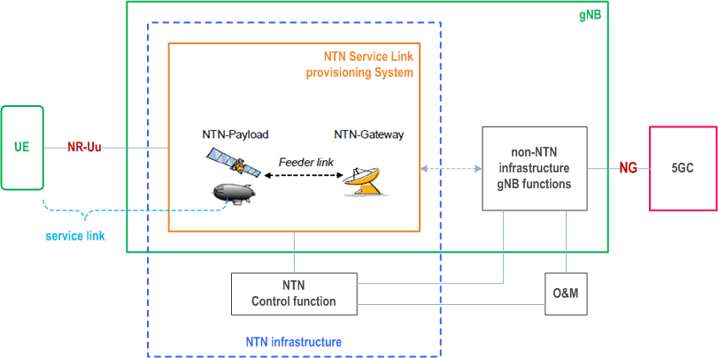
The following Figure illustrates an example implementation of a Non-Terrestrial Network for transparent NTN payload:

The gNB depicted in Figure B.4-1 may be subdivided into non-NTN infrastructure gNB functions and the NTN Service Link provisioning system. The NTN infrastructure may be thought of being subdivided into the NTN Service Link provisioning system and the NTN Control function. The NTN Service Link provisioning system may consist of one or more NTN payloads and NTN Gateways.
The NTN payload is embarked on a spaceborne (or airborne) vehicle, providing a structure, power, commanding, telemetry, attitude control for the satellite (resp. HAPS) and possibly an appropriate thermal environment, radiation shielding.
The NTN Service Link provisioning system maps the NR-Uu radio protocol over radio resources of the NTN infrastructure (e.g. beams, channels, Tx power).
The NTN control function controls the spaceborne (or airborne) vehicles as well as the radio resources of the NTN infrastructure (NTN payload(s) & NTN Gateway(s)). It provides control data, e.g. Ephemeris, to the non-NTN infrastructure gNB functions of the gNB.
Provision of NTN control data to the gNB is out of 3GPP scope.
At least the following NTN related parameters are expected to be provided by O&M to the gNB for its operation:
-
Earth-fixed beams: for each beam provided by a given NTN-payload:
- The Cell identifier (NG and Uu) mapped to the beam;
- The Cell's reference location (e.g. cell's center and range).
- The Cell identifier (NG and Uu) and time window mapped to a beam;
- The Cell's/beam's reference location (e.g. cell's center and range);
- The time window of the successive switch overs (feeder link, service link);
- The identifier and time window of all serving satellites (resp. HAPS) and NTN Gateways.
- The Uu Cell identifier mapped to a beam and mapping information to fixed geographical areas reported on NG, including information about the beams direction and motion of the beam's foot print on Earth;
- Its elevation wrt NTN payload;
- Schedule of successive serving NTN Gateways/gNBs;
- Schedule of successive switch overs (feeder link, service link).