Content for TS 38.300 Word version: 18.2.0
1…
4…
4.7…
5…
5.3…
5.4…
6…
6.2…
6.6…
7…
8…
9…
9.2.2…
9.2.2.5…
9.2.3…
9.2.3.2…
9.2.3.3…
9.2.4…
9.2.6…
9.3…
10…
11…
15…
15.5…
16…
16.2…
16.3…
16.4…
16.8…
16.9…
16.10…
16.12…
16.12.5…
16.12.6…
16.12.6.3
16.12.7
16.13…
16.14…
16.15…
16.18…
16.19…
16.21…
16.21.3…
17…
18…
19
20…
21…
A…
B…
C…
G…
6.6 L2 Data Flow
6.7 Carrier Aggregation
6.8 Dual Connectivity
6.9 Supplementary Uplink
6.10 Bandwidth Adaptation
6.11 Backhaul Adaptation Protocol Sublayer
6.11.1 Services and Functions
6.11.2 Traffic Mapping from Upper Layers to Layer-2
6.11.3 Routing, BAP Header Rewriting and BH-RLC-channel Mapping on BAP sublayer
6.12 Multiple Transmit/Receive Point Operation
...
...
6.6 L2 Data Flow p. 59
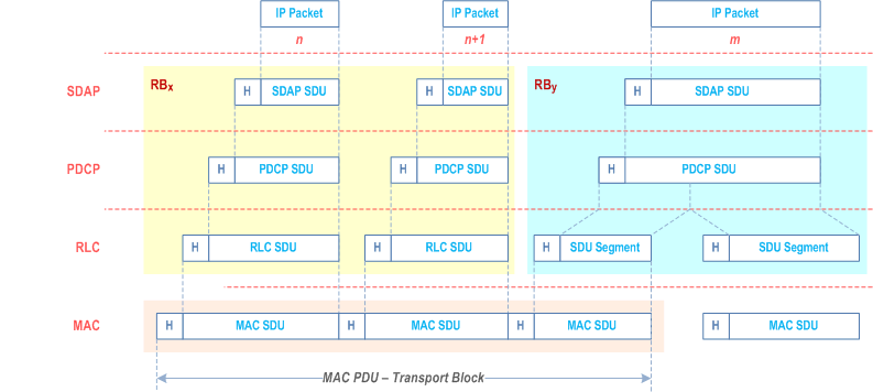
An example of the Layer 2 Data Flow is depicted on Figure 6.6-1, where a transport block is generated by MAC by concatenating two RLC PDUs from RBx and one RLC PDU from RBy. The two RLC PDUs from RBx each corresponds to one IP packet (n and n+1) while the RLC PDU from RBy is a segment of an IP packet (m).
6.7 Carrier Aggregation p. 59
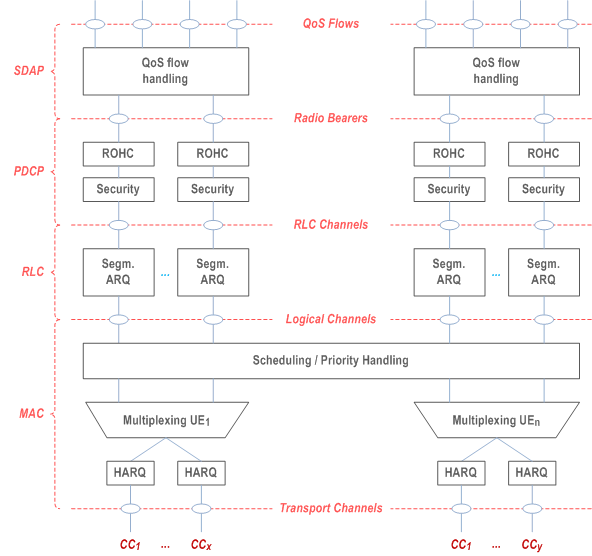
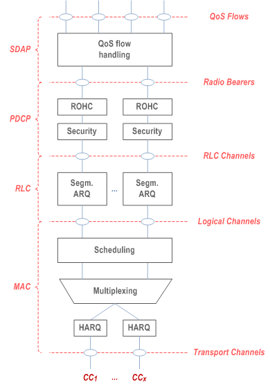
In case of CA, the multi-carrier nature of the physical layer is only exposed to the MAC layer for which one HARQ entity is required per serving cell as depicted on Figure 6.7-1 and Figure 6.7-2 below:
- In both uplink and downlink, there is one independent hybrid-ARQ entity per serving cell and one transport block is generated per assignment/grant per serving cell in the absence of spatial multiplexing. Each transport block and its potential HARQ retransmissions are mapped to a single serving cell.
6.8 Dual Connectivity p. 61
When the UE is configured with SCG, the UE is configured with two MAC entities: one MAC entity for the MCG and one MAC entity for the SCG. Further details of DC operation can be found in TS 37.340.
6.9 Supplementary Uplink p. 61
In case of Supplementary Uplink (SUL, see TS 38.101-1), the UE is configured with 2 ULs for one DL of the same cell, and uplink transmissions on those two ULs are controlled by the network to avoid overlapping PUSCH/PUCCH transmissions in time. Overlapping transmissions on PUSCH are avoided through scheduling while overlapping transmissions on PUCCH are avoided through configuration (PUCCH can only be configured for only one of the 2 ULs of the cell). In addition, initial access is supported in each of the uplink (see clause 9.2.6). An example of SUL is given in Annex B.
6.10 Bandwidth Adaptation p. 61
With Bandwidth Adaptation (BA), the receive and transmit bandwidth of a UE need not be as large as the bandwidth of the cell and can be adjusted: the width can be ordered to change (e.g. to shrink during period of low activity to save power); the location can move in the frequency domain (e.g. to increase scheduling flexibility); and the subcarrier spacing can be ordered to change (e.g. to allow different services). A subset of the total cell bandwidth of a cell is referred to as a Bandwidth Part (BWP) and BA is achieved by configuring the UE with BWP(s) and telling the UE which of the configured BWPs is currently the active one.
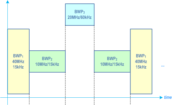
Figure 6.10-1 below describes a scenario where 3 different BWPs are configured:
- BWP1 with a width of 40 MHz and subcarrier spacing of 15 kHz;
- BWP2 with a width of 10 MHz and subcarrier spacing of 15 kHz;
- BWP3 with a width of 20 MHz and subcarrier spacing of 60 kHz.
6.11 Backhaul Adaptation Protocol Sublayer |R16| p. 62
6.11.1 Services and Functions p. 62
The main service and functions of the BAP sublayer include:
- Transfer of data;
- Routing of packets to next hop;
- Determination of BAP destination and BAP path for packets from upper layers;
- Determination of egress BH RLC channels for packets routed to next hop;
- Differentiating traffic to be delivered to upper layers from traffic to be delivered to egress link;
- Flow control feedback and polling signalling;
- BH RLF detection indication, BH RLF recovery indication, and BH RLF indication;
- BAP header rewriting.
6.11.2 Traffic Mapping from Upper Layers to Layer-2 p. 62
In upstream direction, the IAB-donor-CU configures the IAB-node with mappings between upstream F1 and non-F1 traffic originated at the IAB-node, and the appropriate BAP routing ID, next-hop BAP address and BH RLC channel. A specific mapping is configured:
- for each F1-U GTP-U tunnel;
- for non-UE associated F1AP messages;
- for UE-associated F1AP messages;
- for non-F1 traffic.
6.11.3 Routing, BAP Header Rewriting and BH-RLC-channel Mapping on BAP sublayer p. 63
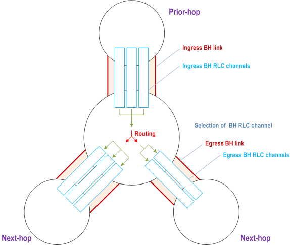
Routing on BAP sublayer uses the BAP routing ID, which is configured by the IAB-donor-CU. The BAP routing ID consists of BAP address and BAP path ID. The BAP address is used for the following purposes:
- Determination if a packet has reached the destination node, i.e. IAB-node or IAB-donor-DU, on BAP sublayer. This is the case if the BAP address in the packet's BAP header matches the BAP address configured via RRC on the IAB-node, or via F1AP on the IAB-donor-DU. For a dual-connected boundary IAB-node that is configured with two BAP addresses, the BAP address in the packet's BAP header is matched with the BAP address configured by the CU of the IAB topology, where the packet has been received.
- Determination of the next-hop node for packets that have not reached their destination. This applies to packets arriving from a prior hop on BAP sublayer or that have been received from IP layer.
| BAP routing ID | Next-hop BAP address |
|---|---|
| Derived from BAP packet's BAP header | Egress BH link to forward packet |
The IAB-node resolves the next-hop BAP address to a physical backhaul link. For this purpose, the IAB-donor-CU provides the IAB-node/IAB-donor-DU with its child-node's BAP address via F1AP, and it provides the IAB-node with its parent-node's BAP address via RRC. For a boundary IAB-node, the routing configuration also indicates the IAB topology it applies to. The BH link to the next-hop node and the next-hop BAP address belong to the IAB topology of the CU that provided the RRC configuration of the BH link to that next-hop node.
The IAB-node can receive multiple routing configurations with the same destination BAP address but different BAP path IDs. These routing configurations may resolve to the same or different egress BH links.
In case the BH link resolved from the routing entry is considered unavailable for this packet, the IAB-node may perform local rerouting as defined in TS 38.340, i.e., select another BH link by considering only the packet's BAP address or, in some cases, by header rewriting. In this manner, the packet can be delivered via an alternative path as defined in TS 38.340.
A BH link may be considered unavailable in case the BH link has RLF. A parent link may be considered unavailable after a BH RLF detection indication has been received on this parent link and before a subsequent BH RLF recovery indication has been received on the same parent link. For DL traffic, a BH link may be considered unavailable for BAP PDUs carrying a certain BAP routing ID due to congestion derived from flow-control feedback information related to this BAP routing ID, as defined in TS 38.340.
For a boundary IAB-node, the routing configuration may carry information on the IAB topology the configuration applies to.
The IAB-node may rewrite the BAP routing ID in the packet's BAP header under the following circumstances:
- A packet is routed between two IAB topologies via a boundary IAB-node as defined in TS 38.401. In this case, the BAP routing ID carried by the received BAP PDU is allocated by the IAB-donor-CU of the ingress IAB topology, while the BAP routing ID carried by the BAP PDU after header rewriting is allocated by the IAB-donor-CU of the egress IAB topology.
- An upstream packet is locally re-routed to a different IAB-donor-DU than indicated by the BAP address in the BAP header of the received packet. The rewritten BAP header carries the BAP address of the alternative IAB-donor-DU and the BAP path ID for a path to this alternative IAB-donor-DU. BAP header rewriting for upstream inter-IAB-donor-DU local rerouting is only applied if neither routing nor local re-routing without header rewriting resolve to an available egress BH link.
| Ingress BAP routing ID | Egress BAP routing ID | Egress topology indicator |
|---|---|---|
| BAP routing ID carried in the BAP header of the received BAP PDU | BAP routing ID carried in the BAP header of the transmitted BAP PDU | Indicates the egress IAB topology. |
For upstream packets that are locally re-routed to a different IAB-donor-DU, the BAP header is rewritten with a BAP routing ID contained in the routing entry that was selected for re-routing.
Details of BAP header rewriting are defined in TS 38.340.
When routing a packet from an ingress to an egress BH link, the IAB-node derives the egress BH RLC channel on the egress BH link through an F1AP-configured mapping from the BH RLC channel used on the ingress BH link. The BH RLC channel IDs used for ingress and egress BH RLC channels are generated by the IAB-donor-CU. Since the BH RLC channel ID only has link-local scope, the mapping configurations also include the BAP addresses of prior and next hop:
| Next-hop BAP address | Prior-hop BAP address | Ingress RLC channel ID | Egress RLC channel ID |
|---|---|---|---|
| Derived from routing configuration | Derived from packet's ingress BH link | Derived from packet's ingress BH RLC channel | BH RLC channel on egress BH link to forward packet |
For a boundary IAB-node, the BH RLC channel mapping configuration may also include indicators for the IAB topology of the ingress and of the egress BH link.
The IAB-node resolves the BH RLC channel IDs from logical channel IDs based on the configuration by the IAB-donor-CU. The IAB-MT obtains the BH RLC channel ID in the RRC configuration of the corresponding logical channel. The IAB-DU obtains the BH RLC channel ID in the F1AP configuration of the BH RLC channel.
6.12 Multiple Transmit/Receive Point Operation |R16| p. 65
In Multiple Transmit/Receive Point (multi-TRP) operation, a serving cell can schedule the UE from two TRPs, providing better coverage, reliability and/or data rates for PDSCH, PDCCH, PUSCH, and PUCCH.
There are two different operation modes to schedule multi-TRP PDSCH transmissions: single-DCI and multi-DCI. For both modes, control of uplink and downlink operation can be done by physical layer and MAC layer, within the configuration provided by the RRC layer. In single-DCI mode, the UE is scheduled by the same DCI for both TRPs and in multi-DCI mode, the UE is scheduled by independent DCIs from each TRP.
There are two different operation modes for multi-TRP PDCCH: PDCCH repetition as in Clause 5.2.3 and Single Frequency Network (SFN) based PDCCH transmission. In both modes, the UE can receive two PDCCH transmissions, one from each TRP, carrying the same DCI. In PDCCH repetition mode, the UE can receive the two PDCCH transmissions carrying the same DCI from two linked search spaces each associated with a different CORESET. In SFN based PDCCH transmission mode, the UE can receive the two PDCCH transmissions carrying the same DCI from a single search space/CORESET using different TCI states.
For multi-TRP PUSCH repetition, according to indications in a single DCI or in a semi-static configured grant provided over RRC, the UE performs PUSCH transmission of the same contents toward two TRPs with corresponding beam directions associated with different spatial relations. For multi-TRP PUCCH repetition, the UE performs PUCCH transmission of the same contents toward two TRPs with corresponding beam directions associated with different spatial relations.
For inter-cell multi-TRP operation, for multi-DCI PDSCH transmission, one or more TCI states can be associated with SSB with a PCI different from the serving cell PCI. The activated TCI states can be associated with at most one PCI different from the serving cell PCI at a time.
For inter-cell and intra-cell multi-DCI multi-TRP operation, up to two TAGs with associated TAG IDs can be configured per serving cell. Each UL/Joint TCI state is associated with a TAG ID and the UE applies the timing advance of the TAG ID associated with the UL/joint TCI state utilized for UL transmission.
For single-DCI multi-TRP Simultaneous Transmission with Multi-Panel (STxMP) Spatial Domain Multiplexing (SDM) PUSCH transmission, different layers of one PUSCH are separately transmitted towards two TRPs. For single-DCI multi-TRP STxMP SFN PUSCH transmission, same layers of one PUSCH are transmitted towards two TRPs. For multi-DCI based multi-TRP STxMP PUSCH+PUSCH transmission, two PUSCHs are transmitted towards two TRPs. For single-DCI multi-TRP STxMP SFN PUCCH transmission, one PUCCH is transmitted towards two TRPs.