Content for TS 38.300 Word version: 18.2.0
1…
4…
4.7…
5…
5.3…
5.4…
6…
6.2…
6.6…
7…
8…
9…
9.2.2…
9.2.2.5…
9.2.3…
9.2.3.2…
9.2.3.3…
9.2.4…
9.2.6…
9.3…
10…
11…
15…
15.5…
16…
16.2…
16.3…
16.4…
16.8…
16.9…
16.10…
16.12…
16.12.5…
16.12.6…
16.12.6.3
16.12.7
16.13…
16.14…
16.15…
16.18…
16.19…
16.21…
16.21.3…
17…
18…
19
20…
21…
A…
B…
C…
G…
16.12 Sidelink Relay
16.12.1 General
16.12.2 Protocol Architecture
16.12.2.1 L2 UE-to-Network Relay
16.12.2.2 L2 UE-to-UE Relay
16.12.3 Relay Discovery
16.12.4 Relay Selection/Reselection
...
...
16.12 Sidelink Relay |R17| p. 187
16.12.1 General p. 187
Sidelink relay supports 5G ProSe UE-to-Network Relay (U2N Relay) function (specified in TS 23.304) to provide connectivity to the network for U2N Remote UE(s). Both L2 and L3 U2N Relay architectures are supported. The L3 U2N Relay architecture is transparent to the serving NG-RAN of the U2N Relay UE, except for controlling sidelink resources. The detailed architecture and procedures for L3 U2N Relay can be found in TS 23.304.
A U2N Relay UE shall be in RRC_CONNECTED to perform relaying of unicast data.
For L2 U2N Relay operation, the following RRC state combinations are supported:
- Both L2 U2N Relay UE and L2 U2N Remote UE shall be in RRC_CONNECTED to perform transmission/ reception of relayed unicast data; and
- The L2 U2N Relay UE can be in RRC_IDLE, RRC_INACTIVE or RRC_CONNECTED as long as all the L2 U2N Remote UE(s) that are connected to the L2 U2N Relay UE are either in RRC_INACTIVE or in RRC_IDLE.
16.12.2 Protocol Architecture p. 188
16.12.2.1 L2 UE-to-Network Relay p. 188
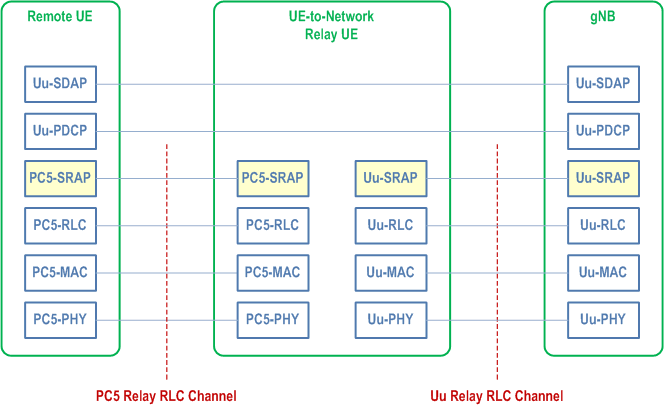
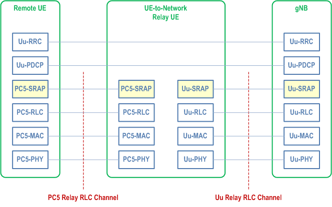
The protocol stacks for the user plane and control plane of L2 U2N Relay architecture are illustrated in Figure 16.12.2.1-1 and Figure 16.12.2.1-2. The SRAP sublayer is placed above the RLC sublayer for both CP and UP at both PC5 interface and Uu interface. The Uu SDAP, PDCP and RRC are terminated between L2 U2N Remote UE and gNB, while SRAP, RLC, MAC and PHY are terminated in each hop (i.e., the link between L2 U2N Remote UE and the L2 U2N Relay UE and the link between L2 U2N Relay UE and the gNB).
For L2 U2N Relay, the SRAP sublayer over PC5 hop is only for the purpose of bearer mapping. The SRAP sublayer is not present over PC5 hop for relaying the L2 U2N Remote UE's message on BCCH and PCCH. For L2 U2N Remote UE's message on SRB0, the SRAP header is not present over PC5 hop, but the SRAP header is present over Uu hop for both DL and UL.
For L2 U2N Relay, for uplink:
- The Uu SRAP sublayer performs UL bearer mapping between end-to-end Uu Radio Bearers of L2 U2N remote UE (identified for the purposes of this mapping by the local Remote UE ID and an associated bearer ID) and egress Uu Relay RLC channels over the L2 U2N Relay UE Uu interface. For uplink relaying traffic, the different end-to-end Uu Radio Bearers (SRBs or DRBs) of the same L2 U2N Remote UE and/or different L2 U2N Remote UEs can be multiplexed over the same egress Uu Relay RLC channel;
- The Uu SRAP sublayer supports L2 U2N Remote UE identification for the UL traffic. The identity information of L2 U2N Remote UE end-to-end Uu Radio Bearer and a local Remote UE ID are included in the Uu SRAP header at UL in order for gNB to correlate the received packets for the specific PDCP entity associated with the right end-to-end Uu Radio Bearer of the L2 U2N Remote UE;
- The PC5 SRAP sublayer at the L2 U2N Remote UE supports UL bearer mapping between L2 U2N Remote UE end-to-end Uu Radio Bearers and egress PC5 Relay RLC channels.
- The Uu SRAP sublayer performs DL bearer mapping at gNB to map end-to-end Uu Radio Bearer (SRB, DRB) of L2 U2N Remote UE (identified for the purposes of this mapping by the local Remote UE ID and an associated bearer ID) into Uu Relay RLC channel. The Uu SRAP sublayer performs DL bearer mapping and data multiplexing between multiple end-to-end Radio Bearers (SRBs or DRBs) of a L2 U2N Remote UE and/or different L2 U2N Remote UEs and one Uu Relay RLC channel over the L2 U2N Relay UE Uu interface;
- The Uu SRAP sublayer supports L2 U2N Remote UE identification for DL traffic. The identity information of L2 U2N Remote UE end-to-end Uu Radio Bearer and a local Remote UE ID are included into the Uu SRAP header by the gNB at DL for the L2 U2N Relay UE to identify the corresponding end-to-end Uu Radio Bearer(s) of L2 U2N Remote UE;
- The PC5 SRAP sublayer at the L2 U2N Relay UE performs DL bearer mapping between end-to-end Uu Radio Bearers of L2 U2N remote UE and egress PC5 Relay RLC channels;
- The PC5 SRAP sublayer at the L2 U2N Remote UE correlates the received packets with the right PDCP entity associated with the given end-to-end Uu Radio Bearer of the L2 U2N Remote UE based on the identity information included in the PC5 SRAP header.
16.12.2.2 L2 UE-to-UE Relay |R18| p. 190
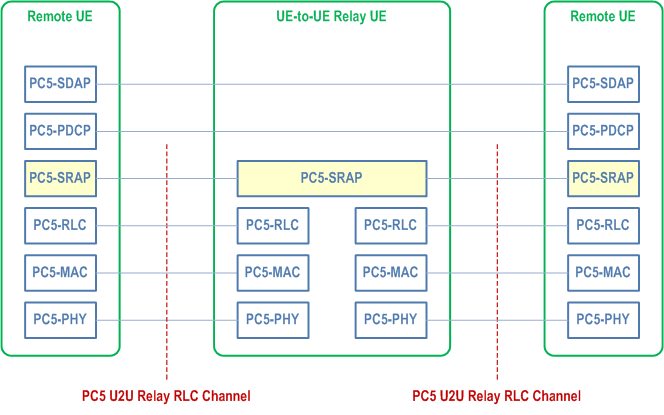
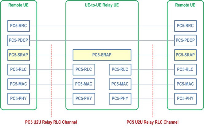
The protocol stacks for the user plane and the control plane of the L2 U2U Relay architecture are illustrated in Figure 16.12.2.2-1 and Figure 16.12.2.2-2. The SRAP sublayer is placed above the RLC sublayer for both CP and UP at both PC5 interfaces. The sidelink SDAP, PDCP and RRC are terminated between two L2 U2U Remote UEs (i.e., end-to-end), while SRAP, RLC, MAC and PHY are terminated in each hop of PC5 link.
For L2 UE-to-UE Relay, the SRAP sublayer at L2 U2U Remote UE:
- The SRAP sublayer at L2 U2U Remote UE performs bearer mapping between end-to-end PC5 Radio Bearers (SL-SRBs or SL-DRBs) of the L2 U2U Remote UE and PC5 Relay RLC Channel at each hop between the L2 U2U Remote UE and the L2 U2U Relay UE.
- For the traffic transmitted from an L2 U2U Remote UE to an L2 U2U Relay UE, the different end-to-end PC5 Radio Bearers (SL-SRBs or SL-DRBs) towards the same peer L2 U2U Remote UE and/or different peer L2 U2U Remote UEs can be multiplexed to the same PC5 Relay RLC channel between the L2 U2U Remote UE(s) and the L2 U2U Relay UE. An end-to-end DRB and an end-to-end SRB cannot be multiplexed to the same PC5 Relay RLC channel.
- For the traffic received at L2 U2U Remote UE, the same PC5 Relay RLC channel from one L2 U2U Relay UE can be de-multiplexed to the different end-to-end PC5 Radio Bearers (SL-SRBs or SL-DRBs) of the same peer L2 U2U Remote UE and/or different peer L2 U2U Remote UEs.
- The SRAP sublayer at L2 U2U Remote UE supports identification of the peer L2 U2U Remote UE and itself. The local IDs are assigned by L2 U2U Relay UE to both L2 U2U Remote UEs for identification. For the two local IDs, one of them identifies L2 U2U Remote UE and the other identifies the peer L2 U2U Remote UE. The local ID of the peer L2 U2U Remote UE and the local ID of L2 U2U Remote UE are delivered by L2 U2U Relay UE to the L2 U2U Remote UEs along with the corresponding L2 ID of the peer L2 U2U Remote UE. The SRAP header includes the identity information of the end-to-end PC5 Radio Bearer and two local IDs. The peer L2 U2U Remote UE matches the received packets with the specific sidelink PDCP entity with the correct end-to-end PC5 Radio Bearer of the L2 U2U Remote UEs.
- The SRAP sublayer at L2 U2U Relay UE determines the egress PC5 Relay RLC Channel based on the mapping of the end-to-end PC5 Radio Bearer and egress PC5 Relay RLC Channel for a particular pair of L2 U2U Remote UE and the peer L2 U2U Remote UE.
- For the ingress traffic received from an/multiple L2 U2U Remote UE(s) at L2 U2U Relay UE, the different end-to-end PC5 Radio Bearers (SL-SRBs or SL-DRBs) of the same L2 U2U Remote UE and/or the same/different end-to-end PC5 Radio Bearers (SL-SRBs or SL-DRBs) of L2 U2U Remote UEs can be multiplexed to the same egress PC5 Relay RLC channel in between the L2 U2U Relay UE and the peer L2 U2U Remote UE. An end-to-end DRB and an end-to-end SRB cannot be multiplexed to the same PC5 Relay RLC channel.
16.12.3 Relay Discovery p. 191
Model A and Model B discovery models as defined in TS 23.304 are supported for U2N/U2U Relay discovery. The protocol stack used for discovery is illustrated in Figure 16.12.3-1.
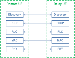
The U2N Remote UE can perform Relay discovery message (i.e., as specified in TS 23.304) transmission and may monitor the sidelink for Relay discovery message while in RRC_IDLE, RRC_INACTIVE or RRC_CONNECTED. The network may broadcast or configure via dedicated RRC signalling a Uu RSRP threshold, which is used by the U2N Remote UE to determine if it can transmit Relay discovery messages to U2N Relay UE(s).
The U2N Relay UE can perform Relay discovery message (i.e., as specified in TS 23.304) transmission and may monitor the sidelink for Relay discovery message while in RRC_IDLE, RRC_INACTIVE or RRC_CONNECTED. The network may broadcast or configure via dedicated RRC signalling a maximum Uu RSRP threshold, a minimum Uu RSRP threshold, or both, which are used by the U2N Relay UE to determine if it can transmit Relay discovery messages to U2N Remote UE(s).
The U2U Remote UE and U2U Relay UE can perform Relay discovery message transmission or DCR/DCA message with integrated discovery transmission and may monitor for Relay discovery message or DCR/DCA message with integrated discovery while in coverage (i.e. RRC_IDLE, RRC_INACTIVE, or RRC_CONNECTED) or out-of-coverage.
The network may provide the Relay discovery configuration using broadcast or dedicated signalling. In addition, the U2N/U2U Remote UE, L3 U2N Relay UE and U2U Relay UE may use pre-configuration for Relay discovery.
The resource pool(s) used for NR sidelink communication can be used for Relay discovery or the network may configure resource pool(s) dedicated for Relay discovery. Resource pool(s) dedicated for Relay discovery can be configured simultaneously with resource pool(s) for NR sidelink communication in system information, dedicated signalling and/or pre-configuration. Whether dedicated resource pool(s) for Relay discovery are configured is based on network implementation. If resource pool(s) dedicated for Relay discovery are configured, only those resource pool(s) dedicated for Relay discovery shall be used for Relay discovery. If only resource pool(s) for NR sidelink communication are configured, all the configured resource pool(s) can be used for Relay discovery and NR sidelink communication. Only the resource pool for NR sidelink communication is used for the DCR/DCA message with integrated discovery.
For U2N Remote UE (including both in-coverage and out of coverage cases) that has been connected to the network via a U2N Relay UE, only resource allocation mode 2 is used for Relay discovery message transmission.
For in-coverage U2N Relay UE, and for both in-coverage and out of coverage U2N Remote UEs, NR sidelink resource allocation principles are applied for Relay discovery message transmission.
For U2U Remote UE and U2U Relay UE, NR sidelink resource allocation principles, both mode 1 and mode 2, can be applied for Relay discovery message transmission.
The sidelink power control for the transmission of Relay discovery messages is same as for NR sidelink communication.
No ciphering or integrity protection in PDCP layer is applied for the Relay discovery messages.
The U2N/U2U Remote UE and U2N/U2U Relay UE can determine from SIB12 whether the gNB supports Relay discovery, or Non-Relay discovery, or both.
16.12.4 Relay Selection/Reselection p. 193
The U2N Remote UE performs radio measurements at PC5 interface and uses them for U2N Relay selection and reselection along with higher layer criteria, as specified in TS 23.304. When there is no unicast PC5 connection between the U2N Relay UE and the U2N Remote UE, the U2N Remote UE uses SD-RSRP measurements to evaluate whether PC5 link quality towards a U2N Relay UE satisfies relay selection criterion.
For relay reselection, U2N Remote UE uses SL-RSRP measurements towards the serving U2N Relay UE for relay reselection trigger evaluation when there is data transmission from U2N Relay UE to U2N Remote UE, and it is left to UE implementation whether to use SL-RSRP or SD-RSRP for relay reselection trigger evaluation in case of no data transmission from U2N Relay UE to U2N Remote UE.
A U2N Relay UE is considered suitable by a U2N Remote UE in terms of radio criteria if the PC5 link quality measured by U2N Remote UE towards the U2N Relay UE exceeds configured threshold (pre-configured or provided by gNB). The U2N Remote UE searches for suitable U2N Relay UE candidates that meet all AS layer and higher layer criteria (see TS 23.304). If there are multiple such suitable U2N Relay UEs, it is up to U2N Remote UE implementation to choose one U2N Relay UE among them. For L2 U2N Relay (re)selection, the PLMN ID and cell ID can be used as additional AS criteria.
The U2N Remote UE triggers U2N Relay selection in following cases:
- Direct Uu signal strength of current serving cell of the U2N Remote UE is below a configured signal strength threshold;
- Indicated by upper layer of the U2N Remote UE.
- PC5 signal strength of current U2N Relay UE is below a (pre)configured signal strength threshold;
- Cell reselection, handover, Uu RLF, or Uu RRC connection establishment/resume failure has been indicated by U2N Relay UE via PC5-RRC signalling;
- When U2N Remote UE receives a PC5-S link release message from U2N Relay UE;
- When U2N Remote UE detects PC5 RLF;
- Indicated by upper layer.
- When the SL-RSRP or SD-RSRP between U2U Remote UEs is below a (pre)configured signal strength threshold;
- When U2U Remote UE receives an indication to trigger U2U relay selection from the upper layer of the UE.
- When the SL-RSRP or SD-RSRP of the current U2U Relay UE is below a (pre)configured signal strength threshold;
- When U2U Remote UE receives an indication from the upper layer due to detecting PC5 RLF;
- When L2 U2U Remote UE receives an indication from the upper layer due to receiving the PC5 RLF indication from the L2 U2U Relay UE;
- When U2U Remote UE receives a PC5-S link release message from U2U Relay UE;
- When U2U Remote UE receives an indication to trigger U2U relay reselection from the upper layer of the UE.