Content for TS 38.300 Word version: 18.2.0
1…
4…
4.7…
5…
5.3…
5.4…
6…
6.2…
6.6…
7…
8…
9…
9.2.2…
9.2.2.5…
9.2.3…
9.2.3.2…
9.2.3.3…
9.2.4…
9.2.6…
9.3…
10…
11…
15…
15.5…
16…
16.2…
16.3…
16.4…
16.8…
16.9…
16.10…
16.12…
16.12.5…
16.12.6…
16.12.6.3
16.12.7
16.13…
16.14…
16.15…
16.18…
16.19…
16.21…
16.21.3…
17…
18…
19
20…
21…
A…
B…
C…
G…
16.21.3 Control plane procedure for multi-path relaying
16.21.3.1 Path Management
16.21.3.2 Path Failure Report
16.21.3.3 System Information
16.22 Support of 2Rx XR devices
...
...
16.21.3 Control plane procedure for multi-path relaying p. 225
16.21.3.1 Path Management p. 225
The L2 MP Remote UE needs to establish both a direct path and an indirect path. The L2 MP Remote UE adds the indirect path using PC5 link on top of the direct path under the same gNB. And also, the L2 MP Remote UE using PC5 link adds the direct path on top of the indirect path under the same gNB.
Meanwhile, the L2 MP Remote UE adds the indirect path using N3C link on top of the only direct path under the same gNB. But it is not allowed that the L2 MP Remote UE using N3C indirect path adds the direct path on top of the indirect path. The MP Relay UE using N3C indirect path is restricted to serve only one L2 MP Remote UE.
For L2 MP Remote UE, the direct path and the indirect path should be in the same gNB. The primary path of split SRB1 and SRB2 is always configured on direct path. In the L2 MP Remote UE, non-split SRB1/2 is allowed to be configured only on direct path.
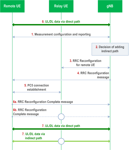
Figure 16.21.3.1-1 describes the procedures for the indirect path addition on top of the direct path for the L2 MP relaying. This procedure is applicable to the L2 MP Remote UE using SL indirect path or N3C indirect path (except step 5).

Step 0.
In the case that the selected L2 MP Relay UE for indirect path addition is in RRC_IDLE or RRC_INACTIVE, after receiving the path addition command, the L2 MP Remote UE should trigger the L2 MP Relay UE in RRC_IDLE or RRC_INACTIVE to move to RRC_CONNECTED. If the L2 MP Remote UE and L2 MP Relay UE are connected by using N3C link, it is L2 MP Remote/Relay UE's implementation on how to trigger the RRC_IDLE/RRC_INACTIVE L2 MP Relay UE to initiate RRC connection establishment/resume procedure.
If the split SRB1 with duplication is not configured at the L2 MP Remote UE, the L2 MP Remote UE using SL indirect path sends PC5-RRC message to the L2 MP Relay UE. Upon receiving the PC5-RRC message, the L2 MP Relay UE in RRC_IDLE or RRC_INACTIVE initiates a Uu RRC connection establishment or an RRC connection resume.
If the split SRB1 with duplication is configured, the L2 MP Remote UE sends the RRCReconfigurationComplete message via the L2 MP Relay UE. The RRCReconfigurationComplete message triggers that the L2 U2N Relay UE in RRC_IDLE or RRC_INACTIVE initiates a Uu RRC connection establishment or an RRC connection resume for sending the RRCReoncfigurationComplete message to the gNB.
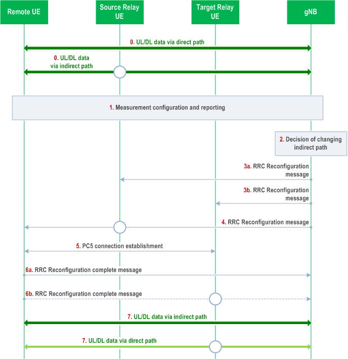
Figure 16.21.3.1-2 describes the procedures for the indirect path change under a single direct path in the L2 MP Relay operation. This procedure is applicable to the L2 MP Remote UE using SL indirect path or N3C indirect path (except step 5).
The L2 MP Remote UE performs data transmission and reception by using direct path on PCell.
Step 1.
If the L2 MP Remote UE will be connected with L2 MP Relay UE using PC5 link, the L2 MP Remote UE reports at least the list of the candidate L2 MP Relay UE ID and the cell ID of the candidate L2 MP Relay UEs based on the measurement configuration from the gNB.
Meanwhile, if the MP Remote UE will be connected with L2 MP Relay UE using N3C link, the MP Remote UE reports at least the list of the C-RNTI and the cell ID of the candidate MP Relay UEs using UEAssistanceInformation message to the gNB.
Step 2.
The gNB decides to add the indirect path for the L2 MP Remote UE. The cell serving the direct path and the cell serving the L2 MP Relay UE on the indirect path belong to the same gNB but can be same or different.
Step 3.
The gNB sends an RRCReconfiguration message to the L2 MP Relay UE to configure the indirect path of the L2 MP Remote UE, if the L2 MP Relay UE is in RRC_CONNECTED.
Step 4.
The gNB sends the RRCReconfiguration message to the L2 MP Remote UE.
Step 5.
The L2 MP Remote UE establishes a PC5 unicast link with the target L2 MP Relay UE.
Step 6a.
The L2 MP Remote UE sends the RRCReconfigurationComplete message to the gNB at least via the direct path in order to complete the indirect path addition procedure.
Step 6b.
If a split SRB1 with duplication is configured, the L2 MP Remote UE also sends the RRCReconfigurationComplete message to the gNB via the indirect path served by the L2 MP Relay UE.
Step 7.
The L2 MP Remote UE performs data transmission and reception by using both the direct path on PCell and the indirect path served by a L2 MP Relay UE.

Step 0.
In the case that the selected target L2 MP Relay UE for indirect path change is in RRC_IDLE or RRC_INACTIVE, after receiving the path change command, the L2 MP Remote UE should trigger the target L2 MP Relay UE in RRC_IDLE or RRC_INACTIVE to be in RRC_CONNECTED. If the L2 MP Remote UE and L2 MP Relay UE are connected by N3C link, it is L2 MP Remote/Relay UE's implementation on how to trigger the RRC_IDLE/RRC_INACTIVE L2 MP Relay UE to initiate RRC connection establishment/resume procedure. If the target L2 MP Relay UE is not in RRC_CONNECTED in step 3, the gNB sends an RRCReconfiguration message to the target L2 MP Relay UE after the target L2 MP Relay UE enters RRC_CONNECTED.
If the split SRB1 with duplication is not configured, at the L2 MP Remote UE, the L2 MP Remote UE sends the RRCReconfigurationComplete message only on the direct path in Step 6a. The L2 MP Remote UE using SL indirect path can send a PC5-RRC message to the target L2 MP Relay UE in RRC_IDLE or RRC_INACTIVE after or during Step 5. The target L2 MP Relay UE in RRC_IDLE or RRC_INACTIVE initiates an RRC connection establishment or an RRC connection resume upon receiving the PC5-RRC message from the L2 MP Remote UE. If the target L2 MP Relay UE is in RRC_IDLE or RRC_INACTIVE, the RRCReconfigurationComplete message at Step 6b is sent to the gNB after the target L2 MP Relay UE enters RRC_CONNECTED.
If the split SRB1 with duplication is configured, the L2 MP Remote UE sends the RRCReconfigurationComplete message via the target L2 MP Relay UE. The RRCReconfigurationComplete message triggers that the L2 U2N Relay UE in RRC_IDLE or RRC_INACTIVE initiates an RRC connection establishment or an RRC connection resume for sending the RRCReconfigurationComplete message to the gNB at Step 6b.
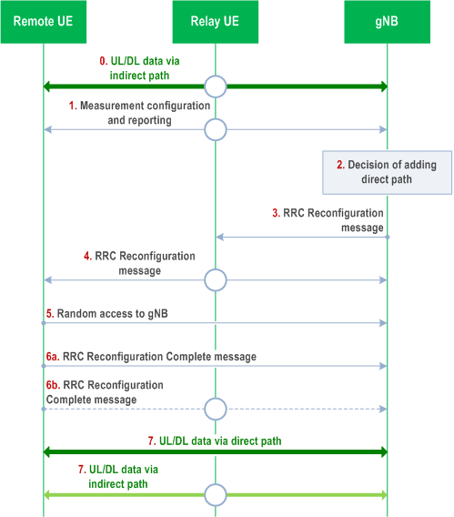
Figure 16.21.3.1-3 describes the procedures for the direct path addition on top of the indirect path for the L2 MP Relay operation. This procedure is only applicable to the L2 MP Remote UE using SL indirect path.
The L2 MP Remote UE performs data transmission and reception by using both the direct path on PCell and the indirect path served by a source L2 MP Relay UE.
Step 1.
The L2 MP Remote UE performs measurements based on measurement configuration. When the measurement reporting is triggered, the L2 MP Remote UE using SL indirect link reports at least signal strength (e.g., SD-RSRP/SL-RSRP) of the serving indirect path, the list of the candidate L2 MP Relay UE ID and the cell ID of the candidate L2 MP Relay UEs.
Meanwhile, the MP Remote UE using N3C link reports at least the list of the C-RNTI and the cell ID of the candidate MP Relay UEs.
Step 2.
The gNB decides to change the indirect path of L2 MP Remote UE from the source L2 MP Relay UE to a target L2 MP Relay UE. The cell serving the direct path and the cell serving the source/target L2 MP Relay UE on the indirect path belong to the same gNB but can be same or different.
Step 3a.
The gNB sends an RRCReconfiguration message to the source L2 MP Relay UE to release the indirect path of the L2 MP Remote UE.
Step 3b.
The gNB sends an RRCReconfiguration message to the target L2 MP Relay UE to add the indirect path for the L2 MP Remote UE.
Step 4.
The gNB sends the RRCReconfiguration message to the L2 MP Remote UE on the direct path or both paths for indirect path change. If split SRB1 is configured, it is up to gNB implementation whether the RRCReconfiguration is sent via one of the paths or both paths.
Step 5.
The L2 MP Remote UE establishes a PC5-RRC connection with the target L2 MP Relay UE for using SL indirect path.
Step 6a.
The L2 MP Remote UE sends the RRCReconfigurationComplete message to the gNB at least via the direct path in order to complete the indirect path change procedure.
Step 6b.
If a split SRB1 with duplication is configured, the L2 MP Remote UE also sends the RRCReconfigurationComplete message to the gNB via the indirect path served by the target L2 MP Relay UE.
Step 7.
The L2 MP Remote UE performs data transmission and reception by using both the direct path on PCell and the indirect path served by a target L2 MP Relay UE.

Step 0.
Figure 16.21.3.1-4 describes the procedures for the direct path change on top of the indirect path for the L2 MP Relay operation. This procedure is only applicable to the L2 MP Remote UE using SL indirect path.
The L2 MP Remote UE performs data transmission and reception by using indirect path via PC5 link.
Step 1.
The L2 MP Remote UE performs measurements based on measurement configuration. When the measurement reporting is triggered, the L2 MP Remote UE reports at least the Uu signal strength of neighbour cells with the cell IDs (i.e., NCGI/NCI).
Step 2.
The gNB decides to add the direct path for the L2 MP Remote UE. The cell serving the direct path and the cell serving the L2 MP Relay UE on the indirect path belong to the same gNB but can be same or different.
Step 3.
The gNB sends an RRCReconfiguration message to the L2 MP Relay UE to update the indirect path configuration, if necessary.
Step 4.
The gNB sends the RRCReconfiguration message to the L2 MP Remote UE via the L2 MP Relay UE. The contents in the RRCReconfiguration message includes at least a target cell within direct path addition configuration.
Step 5.
The L2 MP Remote UE synchronizes to DL of the target cell serving the direct path and performs random access procedure towards the cell serving the direct path. The L2 MP Remote UE configures the target cell as PCell.
Step 6a.
The L2 MP Remote UE sends the RRCReconfigurationComplete message to the gNB at least via the direct path in order to complete the direct path addition procedure.
Step 6b.
If a split SRB1 with duplication is configured, the L2 MP Remote UE also sends the RRCReconfigurationComplete message to the gNB via the indirect path served by the L2 MP Relay UE.
Step 7.
The L2 MP Remote UE performs data transmission and reception by using both the direct path on PCell and the indirect path served by a L2 MP Relay UE.

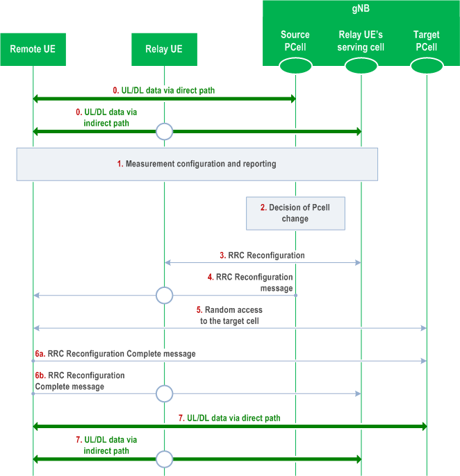
Step 0.
If the direct path addition/change is failed, the L2 U2N Remote UE always shall trigger RRCReestablishment.
The L2 MP Remote UE performs data transmission and reception by using both the direct path on the source PCell and the indirect path served by a L2 MP Relay UE.
Step 1.
The L2 MP Remote UE performs measurements based on measurement configuration. The L2 MP Remote UE may report measurement results.
Step 2.
The gNB decides to change the direct path of the L2 MP Remote UE from the PCell (i.e. source PCell) to a new cell (i.e. target PCell). The source/target PCell serving the old/new direct path and the cell serving the L2 MP Relay UE on the indirect path belong to the same gNB but can be same or different.
Step 3.
The gNB sends an RRCReconfiguration message to the L2 MP Relay UE to update the indirect path configuration, if necessary.
Step 4.
The gNB sends the RRCReconfiguration message to the L2 MP Remote UE on the direct path and/or the indirect path for direct path change.
Step 5.
The L2 MP Remote UE synchronizes to DL of the target PCell serving the new direct path and performs random access procedure towards the target PCell serving the new direct path.
Step 6a.
The L2 MP Remote UE sends the RRCReconfigurationComplete message to the gNB at least via the direct path in order to complete the direct path change procedure.
Step 6b.
If a split SRB1 with duplication is configured, the L2 MP Remote UE also sends the RRCReconfigurationComplete message to the gNB via the indirect path served by the L2 MP Relay UE.
Step 7.
The L2 MP Remote UE performs data transmission and reception by using both the direct path on the target PCell and the indirect path served by a L2 MP Relay UE.
16.21.3.2 Path Failure Report p. 230
The L2 MP Remote UE in RRC_CONNECTED performs Uu RLM (as described in clause 9.2.7).
When the L2 MP Remote UE detects Uu Radio Link Failure (RLF) on the direct path, the L2 MP Remote UE triggers path failure reporting through the indirect path via a RRC message if split SRB1 is configured and the indirect path is not suspended. Otherwise, RRC connection re-establishment is initiated.
When the L2 MP Remote UE using PC5 indirect path detects PC5 Radio Link Failure (RLF) and/or Uu link failure on the indirect path, the L2 MP Remote UE triggers path failure reporting through the direct path via a RRC message, if the direct path is not suspended.
When the L2 MP Remote UE using N3C indirect path detects N3C link failure and/or Uu link failure on the indirect path, the L2 MP Remote UE triggers path failure reporting through the direct path via a RRC message, if the direct path is not suspended.
16.21.3.3 System Information p. 230
The L2 MP Remote UE can acquire any necessary SIB(s) over Uu interface or indirect path. If common search space for system information is configured with the active BWP on PCell, the L2 MP Remote UE can perform direct system information acquisition on PCell. The L2 MP Remote UE can also receive system information at lease PBCH/MIB on the direct path and directly acquires SFN from MIB on the direct path. Besides, the L2 MP Remote UE can receive the system information via dedicated RRC signalling via SRB1.
16.22 Support of 2Rx XR devices |R18| p. 231
16.22.1 Introduction p. 231
A 2Rx XR UE is an XR UE that is not (e)RedCap and is equipped with only two Rx antenna ports in frequency bands where 4Rx antenna ports are mandated as specified in TS 38.101-1, in which it is also defined as two antenna port XR UE. No other relaxations in UE capabilities are allowed for 2Rx XR UEs.
2Rx XR UEs are intended only for use in XR devices that are worn on human head and whose constrained form factors have limited volume available for Rx chains.
16.22.2 Identification, access and camping restrictions p. 231
A UE capability indicates that the UE is a 2Rx XR UE. A 2Rx XR UE does not identify itself in Msg1 or Msg3 during RACH procedure.
Network indicates whether access to a cell by 2Rx XR UEs is barred via system information. For a cell that operates in a frequency band where 4Rx antenna ports are mandated, presence of this indication in its system information indicates that the cell does not allow 2Rx XR UEs. In addition, an IFRI specific for 2Rx XR UEs can be provided in system information. Information on which neighbor frequencies 2Rx XR UEs are allowed to access can be provided in system information.