Content for TS 38.300 Word version: 18.2.0
1…
4…
4.7…
5…
5.3…
5.4…
6…
6.2…
6.6…
7…
8…
9…
9.2.2…
9.2.2.5…
9.2.3…
9.2.3.2…
9.2.3.3…
9.2.4…
9.2.6…
9.3…
10…
11…
15…
15.5…
16…
16.2…
16.3…
16.4…
16.8…
16.9…
16.10…
16.12…
16.12.5…
16.12.6…
16.12.6.3
16.12.7
16.13…
16.14…
16.15…
16.18…
16.19…
16.21…
16.21.3…
17…
18…
19
20…
21…
A…
B…
C…
G…
16.10 Multicast and Broadcast Services
16.10.1 General
16.10.2 Network Architecture
16.10.3 Protocol Architecture
16.10.4 Group Scheduling
16.10.5 Multicast Handling
16.10.5.1 Session Management
16.10.5.2 Configuration
16.10.5.3 Service Continuity
16.10.5.3.1 General
16.10.5.3.2 Handover between Multicast supporting cells
16.10.5.3.3 Handover between Multicast-supporting cell and Multicast non-supporting cell
16.10.5.3.4 MRB reconfiguration
16.10.5.3.5 Service Continuity in RRC_INACTIVE
16.10.5.4 Reception of MBS Multicast data
16.10.5.5 Support of CA
16.10.5.6 DRX
16.10.5.7 Physical Layer
16.10.6 Broadcast Handling
16.10.6.1 Session Management
16.10.6.2 Configuration
16.10.6.3 Support of CA
16.10.6.4 DRX
16.10.6.5 Service Continuity
16.10.6.5.0 General
16.10.6.5.1 Service Continuity in RRC_IDLE or RRC_INACTIVE
16.10.6.5.2 Service Continuity in RRC_CONNECTED
16.10.6.5A Reception of MBS Broadcast data
16.10.6.6 Physical Layer
16.10.6.7 Shared processing for MBS broadcast and unicast reception
16.10.6.8 Support of Resource Sharing across multiple Broadcast MBS sessions in RAN Sharing Scenario
16.11 Minimization of Service Interruption
...
...
16.10 Multicast and Broadcast Services |R17| p. 177
16.10.1 General p. 177
NR system enables resource efficient delivery of multicast/broadcast services (MBS).
For broadcast communication service, the same service and the same specific content data are provided simultaneously to all UEs in a geographical area (i.e., all UEs in the broadcast service area as defined in TS 23.247 are authorized to receive the data). A broadcast communication service is delivered to the UEs using a broadcast session. A UE can receive a broadcast communication service in RRC_IDLE, RRC_INACTIVE and RRC_CONNECTED state.
For multicast communication service, the same service and the same specific content data are provided simultaneously to a dedicated set of UEs (i.e., not all UEs in the MBS service area as defined in TS 23.247 are authorized to receive the data). A multicast communication service is delivered to the UEs using a multicast session. A UE can receive a multicast communication service in RRC_CONNECTED state with mechanisms such as PTP and/or PTM delivery and/or in RRC_INACTIVE state with PTM delivery, as defined in clause 16.10.5.4. HARQ feedback/retransmission can be applied to both PTP and PTM transmission in RRC_CONNECTED state.
16.10.2 Network Architecture p. 177
The overall NG-RAN architecture specified in clause 4 applies for NR MBS. MBS multicast can only be supported in MCG side in NE-DC and NR-DC scenarios, i.e., only for MN-terminated MCG MRB. The configuration of MBS broadcast on SCG is not supported for the UE.
The QoS model for NR MBS can be found in TS 23.247.
16.10.3 Protocol Architecture p. 177
Figure 16.10.3-1 and Figure 16.10.3-2 depict the downlink Layer 2 architecture for multicast session and broadcast session respectively, where MBS protocol stack comprises the same layer 2 sublayers as described in clause 6 with the following differences:
-
SDAP sublayer provides only the following functionalities:
- Mapping between an MBS QoS flow and an MRB;
- Transfer of user plane data.
-
PDCP sublayer provides only the following functionalities:
- Transfer of user plane data;
- Maintenance of PDCP SNs;
- Header compression and decompression using the ROHC protocol or EHC protocol;
- Reordering and in-order delivery;
- Duplicate discarding.
-
For a multicast session, gNB provides one or more of the following multicast MRB configuration(s) to the UE in RRC_CONNECTED state via dedicated RRC signalling:
- Multicast MRB with DL only RLC-UM or bidirectional RLC-UM configuration for PTP transmission;
- Multicast MRB with RLC-AM entity configuration for PTP transmission;
- Multicast MRB with DL only RLC-UM entity for PTM transmission;
- Multicast MRB with two RLC-UM entities, one DL only RLC-UM entity for PTP transmission and the other DL only RLC-UM entity for PTM transmission;
- Multicast MRB with three RLC-UM entities, one DL RLC-UM entity and one UL RLC-UM entity for PTP transmission and the other DL only RLC-UM entity for PTM transmission;
- Multicast MRB with two RLC entities, one RLC-AM entity for PTP transmission and the other DL only RLC-UM entity for PTM transmission.
- For a multicast session, gNB may change the MRB type for the UE in RRC_CONNECTED state using RRC signalling.
-
For a multicast session, gNB provides the following multicast MRB configuration to the UE in RRC_INACTIVE state via broadcast RRC signalling and/or dedicated RRC signalling:
- Multicast MRB with DL only RLC-UM entity for PTM transmission.
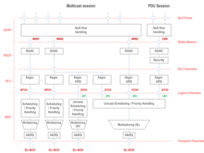
- Broadcast MRB with one DL only RLC-UM entity for PTM transmission.
16.10.4 Group Scheduling p. 179
The following logical channels are used for MBS delivery:
- MTCH: A PTM downlink channel for transmitting MBS data of either multicast session or broadcast session from the network to the UE;
- DTCH: A PTP channel defined in clause 6.2.2 for transmitting MBS data of a multicast session from the network to the UE;
- MCCH: A PTM downlink channel used for transmitting MBS broadcast or MBS multicast control information associated to one or several MTCH(s) from the network to the UE. Broadcast MCCH and multicast MCCH are independent channels. The multicast MCCH is used only for multicast reception in RRC_INACTIVE state.
- MCCH can be mapped to DL-SCH;
- MTCH can be mapped to DL-SCH.
- A UE can receive different services using same or different G-RNTIs;
- A UE can receive different services using same or different G-CS-RNTIs.
16.10.5 Multicast Handling p. 180
16.10.5.1 Session Management p. 180
There are two delivery modes as specified in TS 23.247:
- 5GC Shared MBS traffic delivery;
- 5GC Individual MBS traffic delivery.
- unicast transport;
- multicast transport.
- derivation of the PDCP COUNT values by means of a DL MBS QFI Sequence Number provided on NG-U. Synchronisation in terms of MBS QoS flow to MRB mapping and PDCP SN size of the corresponding MRB among gNBs are achieved by means of network implementation.
- deployment of a Shared NG-U Termination at NG-RAN, shared among gNBs, which comprises a common entity for assignment of PDCP COUNT values. Synchronisation in terms of MBS QoS flow to MRB mapping and PDCP SN size of the corresponding MRB among gNBs may be achieved by means of network implementation.
16.10.5.2 Configuration p. 180
A UE can be configured to receive data of MBS multicast session only in RRC_CONNECTED state or RRC_INACTIVE state. To receive the multicast service, the UE needs to perform MBS Session Join procedure as specified in TS 23.247. It is up to gNB to decide whether the UE receives data of MBS multicast session in RRC_CONNECTED state or RRC_ INACTIVE state. The gNB moves the UE from RRC_CONNECTED state to RRC_INACTIVE state via RRCRelease message, and moves the UE from RRC_INACTIVE state to RRC_CONNECTED state via group notification or UE-specific paging.
If the UE which joined a multicast session is in RRC_CONNECTED state and when the multicast session is activated, the gNB may send RRCReconfiguration message with relevant MBS configuration for the multicast session to the UE.
If the gNB configures the UE to receive the MBS multicast session in RRC_INACTIVE state, the gNB may provide the PTM configuration via RRCRelease message for the MBS multicast session as well as information about which multicast service(s) can be continued to be received in RRC_INACTIVE state. The UE does not suspend MRBs of the multicast session indicated to be continued to be received in RRC_INACTIVE state. Multicast MCCH is used in case a cell supports updating PTM configuration or providing PTM configuration to UEs in RRC_INACTIVE state moved from other cells. Otherwise, multicast MCCH can be optionally present.
A notification mechanism is used to announce the change of the multicast MCCH contents due to multicast session modification or session deactivation or due to neighbouring cell information modification. The scheduling information for multicast MCCH reception is provided via SIB24 and optionally via RRCRelease message.
When there is temporarily no data to be sent to the UEs for a multicast session that is active, the gNB may move the UE to RRC_INACTIVE state. When an MBS multicast session is deactivated, the gNB may move the UE in RRC_CONNECTED state to RRC_IDLE or RRC_INACTIVE state. For UEs receiving data of MBS multicast session in RRC_INACTIVE state, the gNB notifies the UE to stop monitoring PDCCH addressed by corresponding G-RNTI via RRCRelease message or multicast MCCH when there is temporarily no data to be sent or when the session is deactivated. gNBs supporting MBS use a group notification mechanism to notify the UEs in RRC_IDLE or RRC_INACTIVE state when a multicast session has been activated by the CN. gNBs supporting MBS use a group notification mechanism to notify the UEs in RRC_INACTIVE state when the session is already activated and the gNB has multicast session data to deliver. If the UE receiving data of MBS multicast session in RRC_INACTIVE state in a cell is notified to stop monitoring PDCCH addressed by G-RNTI for all the joined multicast sessions, the UE does not monitor PDCCH addressed by Multicast MCCH-RNTI until the group notification is received. Upon reception of the group notification that does not indicate multicast reception in RRC_INACTIVE state, the UEs reconnect to the network or resume the connection and transition to RRC_CONNECTED state from either RRC_IDLE state or RRC_INACTIVE state. Upon reception of the group notification that indicates to allow the multicast reception in RRC_INACTIVE state, the UE stays in RRC_INACTIVE state and behaves as specified in TS 38.331. If the UE is notified by both group notification and the UE-specific paging, the UE follows the UE-specific paging and goes to RRC_CONNECTED state.
The group notification is addressed with P-RNTI on PDCCH, and the paging channels are monitored by the UE as described in clause 9.2.5. Paging message for group notification contains MBS session ID which is utilized to page all UEs in RRC_IDLE and RRC_INACTIVE states that joined the associated MBS multicast session, i.e., UEs are not paged individually. The UE stops monitoring for group notifications related to a specific multicast session, i.e., stops checking for the MBS session ID in the Paging message, when the UE enters RRC_CONNECTED state. The UE does not monitor for group notifications for these cases, i.e., once this UE leaves this multicast session or the network requests the UE to leave, or the network releases the multicast session.
If the UE in RRC_IDLE state that joined an MBS multicast session is camping on the gNB not supporting MBS, the UE may be notified by CN-initiated paging where CN pages each UE individually due to session activation or data availability, as described in clause 9.2.5. If the UE in RRC_INACTIVE state that joined MBS multicast session is camping on the gNB not supporting MBS, the UE may be notified individually by RAN-initiated paging due to session activation or data availability, as described in clause 9.2.5.
16.10.5.3 Service Continuity p. 181
16.10.5.3.1 General p. 181
Mobility principles build on existing functionality including functions described in clause 9.2.
16.10.5.3.2 Handover between Multicast supporting cells p. 182
Mobility procedures for multicast reception allow the UE to continue receiving multicast service(s) via PTM or PTP in a new cell after handover.
During handover preparation phase, the source gNB transfers to the target gNB about the MBS multicast sessions the UE has joined in the UE context information. To support provision of local multicast service with location dependent content as specified in TS 23.247, for each active multicast session, service area information per Area Session ID may be provided to the target gNB.
The source gNB may propose data forwarding for some MRBs to minimize data loss and may exchange the corresponding MRB PDCP Sequence Number with the target gNB during the handover preparation:
- The lossless handover for multicast service is supported for the handover between MBS supporting cells if the UE is configured with PTP RLC AM entity in target cell MRB of a UE, regardless of whether the UE is configured with PTP RLC AM entity in the source cell or not.
- In order to support lossless handover for multicast service, the network has to ensure DL PDCP COUNT value synchronization and continuity between the source cell and the target cell. Furthermore, data forwarding from the source gNB to the target gNB and/or PDCP status report provided by a UE for an MRB for multicast session can be used during lossless handover.
16.10.5.3.3 Handover between Multicast-supporting cell and Multicast non-supporting cell p. 182
During an MBS multicast session, at mobility from an MBS-supporting cell to an MBS non-supporting cell, the target gNB sets up PDU Session Resources mapped to the MBS multicast session. The 5GC infers from the absence of an "MBS-support" indication from gNB in the Path Switch Request message (Xn handover) or Handover Request Acknowledge message (NG handover) that MBS multicast data packets delivery has to be switched to 5GC individual MBS traffic delivery as specified in TS 23.247. If data forwarding is applied, the source gNB infers from the handover preparation response message that the target gNB does not support MBS and changes the QFI(s) in the forwarded packets to the associated PDU Session QFI(s) if respective mapping information is available. The source gNB may be aware that the target gNB is non-MBS supporting already before Handover Preparation.
For mobility from MBS non-supporting cell to MBS-supporting cell, the existing Xn/NG handover procedures apply. The 5GC infers from the presence of the "MBS-support" indicator from gNB in the Path Switch Request message (Xn handover) or in the Handover Request Acknowledge message (NG handover) that MBS multicast data packets delivery can be switched from 5GC Individual MBS traffic delivery to 5GC Shared MBS traffic delivery. After Xn handover, the SMF triggers switching MBS multicast data packets delivery from 5GC Individual to 5GC Shared MBS traffic delivery by providing MBS Session IDs joined by the UE to the target gNB by means of the PDU Session Resource Modification procedure. For NG handover, the SMF provides the MBS Session IDs joined by the UE to the target gNB by means of NGAP Handover Request. Minimization of data loss and duplication avoidance may be applied by means of identical MBS QFI SNs received over the shared NG-U tunnel against those received over unicast NG-U tunnels or forwarding tunnels.
Mobility from a multicast-supporting cell to a multicast non-supporting cell can be achieved by switching the MRB to a DRB in the source gNB before a handover.
16.10.5.3.4 MRB reconfiguration p. 183
The gNB may use RRCReconfiguration message to configure or reconfigure a multicast MRB, e.g., add/release/modify the MRB's RLC entities as described in clause 16.10.3. In order to minimize the data loss due to MRB reconfiguration, gNB may configure UE to send a PDCP status report during reconfiguration for MRB type change.
16.10.5.3.5 Service Continuity in RRC_INACTIVE |R18| p. 183
Mobility procedures for multicast reception allow the UE in RRC_INACTIVE state to continue receiving MBS service(s) when changing cells without resuming RRC connection if the PTM configuration of the new cell can be acquired by the UE from the multicast MCCH after cell reselection. During an active MBS multicast session, the UE is required to resume RRC connection to get the PTM configuration if the PTM configuration or multicast MCCH is not provided in the new cell. Even if the UE in RRC_INACTIVE state has received an indication to stop monitoring PDCCH addressed by G-RNTI for an MBS multicast session in the source cell, the UE acquires multicast MCCH in the reselected cell after cell reselection.
The gNB may indicate in the multicast MCCH the list of neighbour cells providing the same MBS multicast service(s) for UEs in RRC_INACTIVE state as provided in the serving cell. This allows the UE, e.g., to resume RRC connection without reading SIB24 and multicast MCCH of the neighbour cell, if the interested service which is activated is not available to the UE in RRC_INACTIVE state.
The gNB may provide an indication on cell PDCP COUNT synchronization for an MBS session with PTM configuration in RRCRelease message. If indicated by the gNB, all cells within the RNA are synchronized in terms of PDCP COUNT value to the MRBs of the corresponding MBS service, and the order of MRBs within the list of multicast MRB configuration for the same MBS multicast session in the multicast MCCH message of the last serving cell and (re)selected cell within the RNA should be consistent. Upon reselection to a cell indicated as synchronized in terms of PDCP COUNT value, the UE does not initialize the PDCP state variables. Otherwise, the UE initializes the PDCP state variables as defined in TS 38.323.
The UE may be configured with dedicated frequency priorities in RRCRelease message which the UE applies during cell reselection while receiving data of MBS multicast session in RRC_INACTIVE state.
The UE receiving multicast session(s) in RRC_INACTIVE state triggers RRC connection resumption if the latest measured RSRP or RSRQ of the serving cell becomes lower than the threshold configured by the network. The threshold can be configured per MBS session via RRCRelease message or multicast MCCH.
16.10.5.4 Reception of MBS Multicast data p. 183
For multicast service, gNB may deliver MBS multicast data packets using the following methods:
- PTP Transmission: gNB individually delivers separate copies of MBS data packets to each UEs independently, i.e., gNB uses UE-specific PDCCH with CRC scrambled by UE-specific RNTI (e.g., C-RNTI) to schedule UE-specific PDSCH which is scrambled with the same UE-specific RNTI.
- PTM Transmission: gNB delivers a single copy of MBS data packets to a set of UEs, e.g., gNB uses group-common PDCCH with CRC scrambled by group-common RNTI to schedule group-common PDSCH which is scrambled with the same group-common RNTI.
16.10.5.5 Support of CA p. 184
UE can be configured to receive MBS multicast data either from a PCell or a single SCell at a time.
16.10.5.6 DRX p. 184
The following DRX configurations for PTM/PTP transmission by RRC_CONNECTED UEs are possible:
- For PTM transmission, multicast DRX is configured per G-RNTI/G-CS-RNTI which is independent of UE-specific DRX;
- For PTP transmission, UE-specific DRX is reused, i.e., UE-specific DRX is used for both unicast transmission and PTP transmission of MBS multicast. For PTM retransmission via PTP, UE monitors PDCCH scrambled by C-RNTI/CS-RNTI during UE-specific DRX's Active Time.
- For PTM transmission, multicast DRX is configured per G-RNTI.
16.10.5.7 Physical Layer p. 184
A CFR configured by RRCReconfiguration message is defined for multicast scheduling as an 'MBS frequency region' with a number of contiguous PRBs confined within and with the same numerology as the DL BWP, and multicast scheduling may have specific characteristics (e.g., PDCCH, PDSCH and SPS configurations). The CFR for the multicast reception in RRC_INACTIVE state and the CFR for broadcast can be configured differently. If one CFR is not completely contained within the other CFR, the UE in RRC_INACTIVE state is not required to receive both broadcast and multicast simultaneously.
Slot-level repetition is optionally supported for multicast MTCH reception in RRC_INACTIVE state. The maximum number of MIMO layers is one for MBS multicast scheduling for UEs in the RRC_INACTIVE state.
Two HARQ-ACK reporting modes are defined for MBS:
- For the first HARQ-ACK reporting mode, the UE generates HARQ-ACK information with ACK value when a UE correctly decodes a transport block or detects a DCI format indicating an SPS PDSCH release; otherwise, the UE generates HARQ-ACK information with NACK value.
- For the second HARQ-ACK reporting mode, the UE does not transmit a PUCCH that would include only HARQ-ACK information with ACK values.
16.10.6 Broadcast Handling p. 184
16.10.6.1 Session Management p. 184
For delivery of location dependent contents of a broadcast session, Area Session ID is included in the NGAP broadcast session resource setup procedure associated with MBS service area information and per Area Session ID NG-U tunnels are established.
The 5GC may also provide information to the NG-RAN node whether the broadcast session is intended to be received by RedCap UEs only, non-RedCap UEs only or both non-RedCap and RedCap UEs. The NG-RAN may take this into account when configuring MBS session resources.
16.10.6.2 Configuration p. 184
MBS broadcast can be received by UEs in RRC_IDLE, RRC_INACTIVE and RRC_CONNECTED state. A UE can receive the MBS configuration for broadcast session (e.g., parameters needed for MTCH reception) via MCCH in RRC_IDLE, RRC_INACTIVE and RRC_CONNECTED state. The parameters needed for the reception of MCCH are provided via System Information.
The following principles govern the MCCH structure:
- MCCH provides the list of all broadcast services with ongoing sessions transmitted on MTCH(s) and the associated information for broadcast session includes MBS session ID, associated G-RNTI scheduling information and information about neighbouring cells providing certain service on MTCH(s). MCCH content is transmitted within periodically occurring time domain windows, referred to as MCCH transmission window defined by MCCH repetition period, MCCH window duration and radio frame/slot offset;
- MCCH uses a modification period and MCCH contents are only allowed to be modified at each modification period boundary; a notification mechanism is used to announce the change of MCCH contents due to broadcast session start, modification or stop and due to neighbouring cell information modification;
- When the UE receives an MCCH change notification, it acquires the updated MCCH in the same MCCH modification period where the change notification is sent.
16.10.6.3 Support of CA p. 185
UE can be configured to receive MBS broadcast data and MCCH either from a PCell or a single SCell at a time. Meanwhile, dedicated RRC signalling is used for providing SIB20 of the SCell i.e., while in RRC_CONNECTED state, UEs need not acquire broadcast SIB20 directly from the SCells.
16.10.6.4 DRX p. 185
Via MCCH, the UE can be configured with a PTM DRX configuration for G-RNTI reception. One PTM DRX configuration can be mapped to more than one G-RNTI.
16.10.6.5 Service Continuity p. 185
16.10.6.5.0 General p. 185
Mobility principles build on existing functionality including functions described in clause 9.2.
NR MBS supports MBS frequency layer prioritization for MBS broadcast sessions. The gNBs may be configured with the MBS FSA ID(s) supported by each of their cells. The gNBs may exchange this information with their neighbours within Xn Setup messages and subsequent Xn Configuration Update messages to help with frequency layer prioritization. The MBS FSA ID is described in TS 23.247.
16.10.6.5.1 Service Continuity in RRC_IDLE or RRC_INACTIVE p. 185
Mobility procedures for MBS reception allow the UE to start or continue receiving MBS service(s) when changing cells. The gNB may indicate in the MCCH the list of neighbour cells providing the same MBS broadcast service(s) as provided in the serving cell. This allows the UE, e.g., to request unicast reception of the service before moving to a cell not providing the MBS broadcast service(s) using PTM transmission. To avoid the need to read MBS broadcast related system information and potentially MCCH on neighbour frequencies, the UE is made aware of which frequency is providing which MBS broadcast services via PTM, through User Service Description, as defined in TS 26.517, or the combination of the following:
- User Service Description (USD);
- SIB21, as defined in clause 7.3.1.
- the UE which is receiving or interested to receive MBS broadcast service(s) via PTM and can only receive these MBS broadcast service(s) via PTM while camping on the frequency providing these MBS broadcast service(s) is allowed to make this frequency highest priority when the conditions described in TS 38.304 are met;
- when the MBS broadcast service(s) which the UE is interested in are no longer available (after the end of the session) or the UE is no longer interested in receiving the service(s), the UE no longer prioritises the frequency providing these MBS broadcast service(s).
16.10.6.5.2 Service Continuity in RRC_CONNECTED p. 186
To ensure service continuity of MBS broadcast, the UE in RRC_CONNECTED state may send MBS Interest Indication to the gNB, consisting of the following information:
- List of MBS frequencies UE is receiving or interested to receive, sorted in decreasing order of interest;
- Priority between the reception of all listed MBS frequencies and the reception of any unicast bearer and multicast MRB;
- List of MBS broadcast services the UE is receiving or interested to receive, in case SIB20 is provided for PCell or SCell.
16.10.6.5A Reception of MBS Broadcast data p. 186
For broadcast service, gNB may deliver Broadcast MBS data packets using the following method:
- PTM Transmission: gNB delivers a single copy of MBS data packets to a set of UEs, e.g., gNB uses group-common PDCCH with CRC scrambled by group-common RNTI to schedule group-common PDSCH which is scrambled with the same group-common RNTI.
16.10.6.6 Physical Layer p. 186
A CFR configured by SIB is defined for broadcast scheduling as an 'MBS frequency region' with a number of contiguous PRBs with a bandwidth equal to or larger than CORESET0, with the same numerology as CORESET0, and broadcast scheduling may have specific characteristics (e.g., PDCCH and PDSCH configurations). The NG-RAN node may configure an additional RedCap CFR when the bandwidth of the configured default CFR exceeds the (e)RedCap UE capability. A UE only monitors one CFR at a time. An (e)RedCap UE monitors the RedCap CFR, if configured, otherwise the (e)RedCap UE monitors the default CFR, if the bandwidth of the default CFR is within the UE capability. The NG-RAN node ensures that a UE does not receive two DCIs simultaneously (i.e., one associated with the RedCap CFR and another associated with the default CFR) with the same G-RNTI or the same MCCH-RNTI.
The maximum number of MIMO layers is one for MBS broadcast scheduling. RB-level rate matching, and RE-level rate matching around LTE-CRS configured by higher layer signalling are supported for MCCH and MTCH. Slot-level repetition is supported for MTCH.
HARQ-ACK feedback is not supported for MBS broadcast.
Only dynamic scheduling is supported for MBS broadcast.
16.10.6.7 Shared processing for MBS broadcast and unicast reception |R18| p. 186
If the UE in RRC_CONNECTED state is receiving or interested to receive an MBS broadcast service from a non-serving cell as described in TS 38.306 , the UE may use MBS Interest Indication message to inform the serving gNB about the parameters used for the non-serving cell broadcast reception as described in TS 38.331. The gNB may enable the sending of the MBS Interest Indication by including an indication in SIB1. The UE may indicate to the serving cell the UE capability for receiving MBS broadcast service from a non-serving cell. It is up to gNB implementation to consider the MBS Interest Indication and the UE capability for receiving MBS broadcast service from a non-serving cell, if indicated, when scheduling the UE.
In case the UE only reports the frequency for broadcast service reception from the non-serving cell in MBS Interest Indication due to some parameters (e.g., SCS, bandwidth) not being available, the UE may transmit updated MBS Interest Indication once the parameters are available to the UE. It is up to network implementation on how to enable the UE to acquire these parameters from the non-serving cell.
16.10.6.8 Support of Resource Sharing across multiple Broadcast MBS sessions in RAN Sharing Scenario |R18| p. 187
NGAP supports resource sharing efficient scheme for broadcast delivery in RAN sharing. Such scheme enables the gNB to identify broadcast MBS sessions from different PLMNs providing identical content. The identification is based on information provided by the involved 5GCs in the Associated Session ID as specified in TS 23.247.
If in the MBS Broadcast Setup Request message an Associated Session ID is received from a 5GC participating in RAN sharing, the gNB uses it to determine whether MBS Session resources can be shared with a broadcast MBS session(s) associated with the same Associated Session ID requested from another 5GC participating in RAN sharing.
The identification of MBS Broadcast Sessions providing identical content may also be based on implementation specific configuration as specified in TS 23.247.
The gNB applying this resource efficiency scheme:
- may decide whether NG-U resources are established towards all involved 5GCs or only some of them;
- resolves different QoS requirements or different S-NSSAIs received from the participating 5GCs in an implementation specific way.
16.11 Minimization of Service Interruption |R17| p. 187
In case of a disaster, a radio access network can experience outage, which can result in that UEs belonging to the network experience service interruptions. For this scenario, another network not affected by the disaster, which during non-disaster situations is considered by the UEs as a forbidden network, can allow roaming of the UEs belonging to the network experiencing such disaster service interruptions. Such roaming is referred to as disaster roaming. This is further described in clause 5.40 of TS 23.501 and clause 3.10 of TS 23.122.
To allow such disaster roaming, a cell can broadcast a list of PLMNs with disaster conditions for which disaster roaming is offered. Disaster roaming service is provided only for the area that covers the area with disaster condition.
Further, to be able to control the load that disaster roaming UEs put on a cell, the cell can broadcast access control parameters applicable specifically for disaster roaming UEs. Access attempts of disaster roaming UEs are based on Access Identity 3. The network can for example set the access control parameters for Access Identity 3 so that access attempts of disaster roaming UEs are more likely to be barred compared to non-disaster roaming UEs.
![]()
![]()
![]()