Content for TS 38.300 Word version: 18.3.0
1…
4…
4.7…
5…
5.3…
5.4…
6…
6.2…
6.6…
7…
8…
9…
9.2.2…
9.2.2.5…
9.2.3…
9.2.3.2…
9.2.3.3…
9.2.4…
9.2.6…
9.3…
10…
11…
15…
15.5…
16…
16.2…
16.3…
16.4…
16.8…
16.9…
16.10…
16.12…
16.12.5…
16.12.6…
16.12.6.3
16.12.7
16.13…
16.14…
16.15…
16.18…
16.19…
16.21…
16.21.3…
17…
18…
19
20…
21…
A…
B…
C…
G…
16.12.7 Control plane procedures for L2 U2U Relay |R18| p. 205
The L2 U2U Remote UE needs to establish end-to-end SL-SRB/DRBs with the peer L2 U2U Remote UE before user plane data transmission.
The following high level connection establishment procedure in Figure 16.12.7-1 applies to a L2 U2U Relay UE, L2 U2U Remote UE and the peer U2U Remote UE:
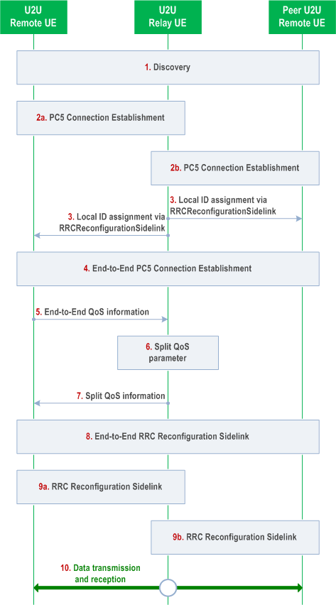
Step 1.
The L2 U2U Remote UE, L2 U2U Relay UE, and peer L2 U2U Remote UE perform discovery procedure or integrated discovery procedure.
Step 2a.
The L2 U2U Remote UE establishes/modifies a PC5-RRC connection with the selected L2 U2U Relay UE (i.e., as specified in TS 23.304).
Step 2b.
The L2 U2U Relay UE establishes/modifies a PC5-RRC connection with the peer L2 U2U Remote UE (i.e., as specified in TS 23.304).
Step 3.
The L2 U2U Relay UE allocates two local IDs and the two local IDs are delivered via RRCReconfigurationSidelink message to each of the L2 U2U Remote UEs: one local ID to identify the L2 U2U Remote UE, the other local ID to identify the peer L2 U2U Remote UE. When the local IDs are delivered, an L2 ID of the peer L2 U2U Remote UE is also delivered to the U2U Remote UE for making the association between the local ID and the L2 ID of the peer U2U Remote UE.
Step 4.
The L2 U2U Remote UE establishes end-to-end PC5-RRC connection with the peer L2 U2U Remote UE via the L2 U2U Relay UE. For the end-to-end connection establishment, fixed indexes (i.e., 0/1/2/3) are defined for end-to-end SL-SRB 0/1/2/3 respectively, and specified PC5 Relay RLC Channel configuration is used on each hop. The sidelink UE capability is exchanged between the L2 U2U Remote UEs via PC5-RRC (e.g., SL-SRB3) message.
Step 5.
The L2 U2U Remote UE obtains PDCP and SDAP configuration for the intended end-to-end SL-DRB(s) via SIB/pre-configuration or dedicated RRC signalling. The L2 U2U Remote UE provides the portion of the configuration related to reception of the end-to-end SL-DRB(s) to the peer L2 U2U Remote UE using end-to-end RRCReconfigurationSidelink message. The end-to-end bearer IDs for SL-SRB and SL-DRB are used as input for the L2 U2U Relay ciphering and integrity protection at SL PDCP.
Step 6.
The L2 U2U Remote UE sends to the L2 U2U Relay UE the QoS profiles for the end-to-end QoS flows and the mapping of the end-to-end QoS flows to SLRB via PC5-RRC message.
Step 7.
The L2 U2U Relay UE performs QoS split only for PDB, per each end-to-end QoS flow.
Step 8.
The L2 U2U Relay UE sends the split QoS value (i.e., PDB) via PC5-RRC message to the L2 U2U Remote UE.
Step 9a.
The L2 U2U Remote UE obtains first hop configuration (e.g. PC5 Relay RLC Channel configuration) for each end-to-end for SL-DRB via dedicated RRC signalling or based on merged first hop QoS in RB-level via SIB/pre-configuration. The L2 U2U Remote UE provides the L2 U2U Relay UE with the configuration related to receiving on the first hop (i.e., Rx by the relay UE), using per-hop RRCReconfigurationSidelink message.
Step 9b.
The L2 U2U Relay UE obtains second hop configuration (e.g. PC5 Relay RLC Channel configuration) for each end-to-end SL-DRB via dedicated RRC signalling or based on merged second hop QoS in RB-level via SIB/pre-configuration. The Relay UE provides the peer L2 U2U Remote UE with the configuration related to receiving on the second hop (i.e., RX by the peer remote UE), using per-hop RRCReconfigurationSidelink message.
Step 10.
The L2 U2U Remote UE and the peer L2 U2U Remote UE transmit or receive data via L2 U2U Relay UE.
![]()
![]()
![]()