Content for TS 38.300 Word version: 18.2.0
1…
4…
4.7…
5…
5.3…
5.4…
6…
6.2…
6.6…
7…
8…
9…
9.2.2…
9.2.2.5…
9.2.3…
9.2.3.2…
9.2.3.3…
9.2.4…
9.2.6…
9.3…
10…
11…
15…
15.5…
16…
16.2…
16.3…
16.4…
16.8…
16.9…
16.10…
16.12…
16.12.5…
16.12.6…
16.12.6.3
16.12.7
16.13…
16.14…
16.15…
16.18…
16.19…
16.21…
16.21.3…
17…
18…
19
20…
21…
A…
B…
C…
G…
9.2.3 Mobility in RRC_CONNECTED p. 87
9.2.3.1 Overview p. 87
Network controlled mobility applies to UEs in RRC_CONNECTED and is categorized into two types of mobility: cell level mobility and beam level mobility. Beam level mobility includes intra-cell beam level mobility and inter-cell beam level mobility.
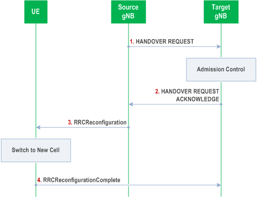
Cell Level Mobility requires explicit RRC signalling to be triggered, i.e. handover. For inter-gNB handover, the signalling procedures consist of at least the following elemental components illustrated in Figure 9.2.3.1-1:

Step 1.
In case of DAPS handover, the UE continues the downlink user data reception from the source gNB until releasing the source cell and continues the uplink user data transmission to the source gNB until successful random access procedure to the target gNB.
Only source and target PCell are used during DAPS handover. CA, DC, SUL, multi-TRP, EHC, CHO, UDC, LTM, NR sidelink configurations and V2X sidelink configurations are released by the source gNB before the handover command is sent to the UE and are not configured by the target gNB until the DAPS handover has completed (i.e. at earliest in the same message that releases the source PCell).
The handover mechanism triggered by RRC requires the UE at least to reset the MAC entity and re-establish RLC, except for DAPS handover, where upon reception of the handover command, the UE:
The source gNB initiates handover and issues a HANDOVER REQUEST over the Xn interface.
Step 2.
The target gNB performs admission control and provides the new RRC configuration as part of the HANDOVER REQUEST ACKNOWLEDGE.
Step 3.
The source gNB provides the RRC configuration to the UE by forwarding the RRCReconfiguration message received in the HANDOVER REQUEST ACKNOWLEDGE. The RRCReconfiguration message includes at least cell ID and all information required to access the target cell so that the UE can access the target cell without reading system information. For some cases, the information required for contention-based and contention-free random access can be included in the RRCReconfiguration message. The access information to the target cell may include beam specific information, if any.
Step 4.
The UE moves the RRC connection to the target gNB and replies with the RRCReconfigurationComplete.
- Creates a MAC entity for target;
- Establishes the RLC entity and an associated DTCH logical channel for target for each DRB configured with DAPS;
- For each DRB configured with DAPS, reconfigures the PDCP entity with separate security and ROHC functions for source and target and associates them with the RLC entities configured by source and target respectively;
- Retains the rest of the source configurations until release of the source.
- When DAPS handover fails, the UE falls back to the source cell configuration, resumes the connection with the source cell, and reports DAPS handover failure via the source without triggering RRC connection re-establishment if the source link has not been released.
- When initial CHO execution attempt fails or HO fails, the UE performs cell selection, and if the selected cell is a CHO candidate and if network configured the UE to try CHO after handover/CHO failure, then the UE attempts CHO execution once, otherwise re-establishment is performed.
- When LTM execution attempt triggered by LTM cell switch command MAC CE fails, the UE performs cell selection and if the selected cell is an LTM candidate cell and if network configured the UE to try LTM after LTM execution failure, then the UE attempts RACH-based LTM execution once, otherwise re-establishment is performed.