Content for TS 38.300 Word version: 18.3.0
1…
4…
4.7…
5…
5.3…
5.4…
6…
6.2…
6.6…
7…
8…
9…
9.2.2…
9.2.2.5…
9.2.3…
9.2.3.2…
9.2.3.3…
9.2.4…
9.2.6…
9.3…
10…
11…
15…
15.5…
16…
16.2…
16.3…
16.4…
16.8…
16.9…
16.10…
16.12…
16.12.5…
16.12.6…
16.12.6.3
16.12.7
16.13…
16.14…
16.15…
16.18…
16.19…
16.21…
16.21.3…
17…
18…
19
20…
21…
A…
B…
C…
G…
9.2.4 Measurements p. 102
In RRC_CONNECTED, the UE measures multiple beams (at least one) of a cell and the measurements results (power values) are averaged to derive the cell quality. In doing so, the UE is configured to consider a subset of the detected beams. Filtering takes place at two different levels: at the physical layer to derive beam quality and then at RRC level to derive cell quality from multiple beams. Cell quality from beam measurements is derived in the same way for the serving cell(s) and for the non-serving cell(s). Measurement reports may contain the measurement results of the X best beams if the UE is configured to do so by the gNB.
The corresponding high-level measurement model is described below:
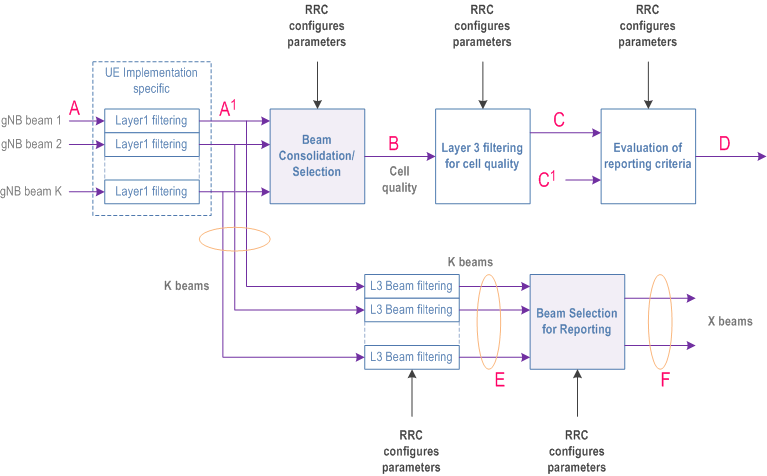
- A: measurements (beam specific samples) internal to the physical layer.
- Layer 1 filtering: internal layer 1 filtering of the inputs measured at point A. Exact filtering is implementation dependent. How the measurements are actually executed in the physical layer by an implementation (inputs A and Layer 1 filtering) is not constrained by the standard.
- A1: measurements (i.e. beam specific measurements) reported by layer 1 to layer 3 after layer 1 filtering.
- Beam Consolidation/Selection: beam specific measurements are consolidated to derive cell quality. The behaviour of the Beam consolidation/selection is standardised and the configuration of this module is provided by RRC signalling. Reporting period at B equals one measurement period at A1.
- B: a measurement (i.e. cell quality) derived from beam-specific measurements reported to layer 3 after beam consolidation/selection.
- Layer 3 filtering for cell quality: filtering performed on the measurements provided at point B. The behaviour of the Layer 3 filters is standardised and the configuration of the layer 3 filters is provided by RRC signalling. Filtering reporting period at C equals one measurement period at B.
- C: a measurement after processing in the layer 3 filter. The reporting rate is identical to the reporting rate at point B. This measurement is used as input for one or more evaluation of reporting criteria.
- Evaluation of reporting criteria: checks whether actual measurement reporting is necessary at point D. The evaluation can be based on more than one flow of measurements at reference point C e.g. to compare between different measurements. This is illustrated by input C and C1. The UE shall evaluate the reporting criteria at least every time a new measurement result is reported at point C, C1. The reporting criteria are standardised and the configuration is provided by RRC signalling (UE measurements).
- D: measurement report information (message) sent on the radio interface.
- L3 Beam filtering: filtering performed on the measurements (i.e. beam specific measurements) provided at point A1. The behaviour of the beam filters is standardised and the configuration of the beam filters is provided by RRC signalling. Filtering reporting period at E equals one measurement period at A1.
- E: a measurement (i.e. beam-specific measurement) after processing in the beam filter. The reporting rate is identical to the reporting rate at point A1. This measurement is used as input for selecting the X measurements to be reported.
- Beam Selection for beam reporting: selects the X measurements from the measurements provided at point E. The behaviour of the beam selection is standardised and the configuration of this module is provided by RRC signalling.
- F: beam measurement information included in measurement report (sent) on the radio interface.
- Measurement reports include the measurement identity of the associated measurement configuration that triggered the reporting;
- Cell and beam measurement quantities to be included in measurement reports are configured by the network;
- The number of non-serving cells to be reported can be limited through configuration by the network;
- Cells belonging to an exclude-list configured by the network are not used in event evaluation and reporting, and conversely when an allow-list is configured by the network, only the cells belonging to the allow-list are used in event evaluation and reporting;
- Beam measurements to be included in measurement reports are configured by the network (beam identifier only, measurement result and beam identifier, or no beam reporting).
- SSB based intra-frequency measurement: a measurement is defined as an SSB based intra-frequency measurement provided the center frequency of the SSB of the serving cell and the center frequency of the SSB of the neighbour cell are the same, and the subcarrier spacing of the two SSBs is also the same.
- SSB based inter-frequency measurement: a measurement is defined as an SSB based inter-frequency measurement provided the center frequency of the SSB of the serving cell and the center frequency of the SSB of the neighbour cell are different, or the subcarrier spacing of the two SSBs is different.
-
CSI-RS based intra-frequency measurement: a measurement is defined as a CSI-RS based intra-frequency measurement provided that:
- The subcarrier spacing of CSI-RS resources on the neighbour cell configured for measurement is the same as the SCS of CSI-RS resources on the serving cell indicated for measurement; and
- For 60kHz subcarrier spacing, the CP type of CSI-RS resources on the neighbour cell configured for measurement is the same as the CP type of CSI-RS resources on the serving cell indicated for measurement; and
- The centre frequency of CSI-RS resources on the neighbour cell configured for measurement is the same as the centre frequency of CSI-RS resource on the serving cell indicated for measurement.
- CSI-RS based inter-frequency measurement: a measurement is defined as a CSI-RS based inter-frequency measurement if it is not a CSI-RS based intra-frequency measurement.
-
For SSB based inter-frequency measurement, if the measurement gap requirement information is reported by the UE, a measurement gap configuration may be provided according to the information. Otherwise, a measurement gap configuration is always provided in the following cases:
- If the UE only supports per-UE measurement gaps;
- If the UE supports per-FR measurement gaps and any of the serving cells are in the same frequency range of the measurement object.
-
For SSB based intra-frequency measurement, if the measurement gap requirement information is reported by the UE, a measurement gap configuration may be provided according to the information. Otherwise, a measurement gap configuration is always provided in the following case:
- Other than the initial BWP, if any of the UE configured BWPs do not contain the frequency domain resources of the SSB associated to the initial DL BWP, and are not configured with NCD-SSB for serving cell measurement.
9.2.5 Paging p. 105
Paging allows the network to reach UEs in RRC_IDLE and in RRC_INACTIVE state through Paging messages, and to notify UEs in RRC_IDLE, RRC_INACTIVE and RRC_CONNECTED state of system information change (see clause 7.3.3) and ETWS/CMAS indications (see clause 16.4) through Short Messages. Both Paging messages and Short Messages are addressed with P-RNTI on PDCCH, but while the former is sent on PCCH, the latter is sent over PDCCH directly (see clause 6.5 of TS 38.331).
While in RRC_IDLE the UE monitors the paging channels for CN-initiated paging. While in RRC_INACTIVE with no ongoing SDT procedure (see clause 18.0) the UE monitors paging channels for RAN-initiated paging and CN-initiated paging. A UE need not monitor paging channels continuously though; Paging DRX is defined where the UE in RRC_IDLE or RRC_INACTIVE is only required to monitor paging channels during one Paging Occasion (PO) per DRX cycle (see TS 38.304). The Paging DRX cycles are configured by the network:
- For CN-initiated paging, a default cycle is broadcast in system information;
- For CN-initiated paging, a UE specific cycle can be configured via NAS signalling;
-
For RAN-initiated paging, a UE-specific cycle is configured via RRC signalling;
- The UE uses the shortest of the DRX cycles applicable i.e. a UE in RRC_IDLE uses the shortest of the first two cycles above, while a UE in RRC_INACTIVE uses the shortest of the three.
at UE context release, the NG-RAN node may provide the AMF with a list of recommended cells and NG-RAN nodes as assistance info for subsequent paging. The AMF may also provide Paging Attempt Information consisting of a Paging Attempt Count and the Intended Number of Paging Attempts and may include the Next Paging Area Scope. If Paging Attempt Information is included in the Paging message, each paged NG-RAN node receives the same information during a paging attempt. The Paging Attempt Count shall be increased by one at each new paging attempt. The Next Paging Area Scope, when present, indicates whether the AMF plans to modify the paging area currently selected at next paging attempt. If the UE has changed its state to CM CONNECTED the Paging Attempt Count is reset.
Paging optimization for UEs in RRC_INACTIVE:
at RAN Paging, the serving NG-RAN node provides RAN Paging area information. The serving NG-RAN node may also provide RAN Paging attempt information. Each paged NG-RAN node receives the same RAN Paging attempt information during a paging attempt with the following content: Paging Attempt Count, the intended number of paging attempts and the Next Paging Area Scope. The Paging Attempt Count shall be increased by one at each new paging attempt. The Next Paging Area Scope, when present, indicates whether the serving NG_RAN node plans to modify the RAN Paging Area currently selected at next paging attempt. If the UE leaves RRC_INACTIVE state the Paging Attempt Count is reset.
UE power saving for paging monitoring:
in order to reduce UE power consumption due to false paging alarms, the group of UEs monitoring the same PO can be further divided into multiple subgroups. With subgrouping, a UE shall monitor PDCCH in its PO for paging if the subgroup to which the UE belongs is paged as indicated via associated PEI. If a UE cannot find its subgroup ID with the PEI configurations in a cell or if the UE is unable to monitor the associated PEI occasion corresponding to its PO, it shall monitor the paging in its PO.
These subgroups have the following characteristics:
- They are formed based on either CN controlled subgrouping or UE ID based subgrouping;
- If CN controlled subgroup ID is not provided from AMF, UE ID based subgrouping is used if supported by the UE and network;
- The RRC state (RRC_IDLE or RRC_INACTIVE state) does not impact which subgroup the UE belongs to;
- Subgrouping support for a cell is broadcast in the system information as one of the following: Only CN controlled subgrouping supported, only UE ID based subgrouping supported, or both CN controlled subgrouping and UE ID based subgrouping supported;
- Total number of subgroups allowed in a cell is up to 8 and represents the sum of CN controlled and UE ID based subgrouping configured by the network;
- A UE configured with CN controlled subgroup ID applies CN controlled subgroup ID if the cell supports CN controlled subgrouping; otherwise, it derives UE ID based subgroup ID if the cell supports only UE ID based subgrouping.
-
If the PEI is supported by the UE, it shall at least support UE ID based subgrouping method;
- PEI monitoring can be limited via system information to the last used cell (i.e., the cell in which the UE most recently received RRCRelease without indicating that the last used cell for PEI shall not be updated);
- A PEI-capable UE shall store its last used cell information;
- gNBs supporting the PEI monitoring to the last used cell function provide the UE's last used cell information to the AMF in the NG-AP UE Context Release Complete message for PEI capable UEs, as described in TS 38.413;
- UE that expects MBS group notification shall ignore the PEI and shall monitor paging in its PO.
For CN controlled subgrouping, AMF is responsible for assigning subgroup ID to the UE. The total number of subgroups for CN controlled subgrouping which can be configured, e.g. by OAM is up to 8. It is assumed that CN controlled subgrouping support is homogeneous within an RNA.
The following Figure describes the procedure for CN controlled subgrouping:
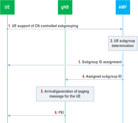
Step 1.
UE ID based subgrouping:
The UE indicates its support of CN controlled subgrouping via NAS signalling.
Step 2.
If the UE supports CN controlled subgrouping, the AMF determines the subgroup ID assignment for the UE.
Step 3.
The AMF sends subgroup ID to the UE via NAS signalling.
Step 4.
The AMF informs the gNB about the CN assigned subgroup ID for paging the UE in RRC_IDLE/ RRC_INACTIVE state.
Step 5.
When the paging message for the UE is received from the CN or is generated by the gNB, the gNB determines the PO and the associated PEI occasion for the UE.
Step 6.
Before the UE is paged in the PO, the gNB transmits the associated PEI and indicates the corresponding CN controlled subgroup of the UE that is to be paged in the PEI.
For UE ID based subgrouping, the gNB and UE can determine the subgroup ID based on the UE ID and the total number of subgroups for UE ID based subgrouping in the cell. The total number of subgroups for UE ID based subgrouping is decided by the gNB for each cell and can be different in different cells. The following Figure describes the procedure for UE ID based subgrouping:
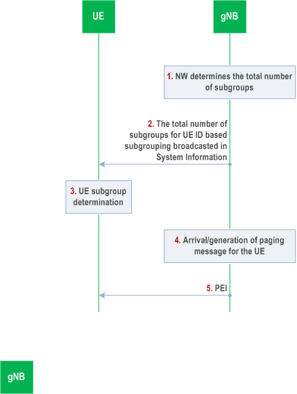
Step 1.
The gNB determines the total number of subgroups for UE ID based subgrouping in a cell.
Step 2.
The gNB broadcasts the total number of subgroups for UE ID based subgrouping in a cell.
Step 3.
UE determines its subgroup in a cell.
Step 4.
When paging message for the PEI capable UE is received from the CN at the gNB or is generated by the gNB, the gNB determines the PO and the associated PEI occasion for the UE.
Step 5.
Before the UE is paged in the PO, the gNB transmits the associated PEI and indicates the corresponding subgroup derived based on UE ID of the UE that is paged in the PEI.
![]()
![]()
![]()