Content for TS 38.300 Word version: 18.2.0
1…
4…
4.7…
5…
5.3…
5.4…
6…
6.2…
6.6…
7…
8…
9…
9.2.2…
9.2.2.5…
9.2.3…
9.2.3.2…
9.2.3.3…
9.2.4…
9.2.6…
9.3…
10…
11…
15…
15.5…
16…
16.2…
16.3…
16.4…
16.8…
16.9…
16.10…
16.12…
16.12.5…
16.12.6…
16.12.6.3
16.12.7
16.13…
16.14…
16.15…
16.18…
16.19…
16.21…
16.21.3…
17…
18…
19
20…
21…
A…
B…
C…
G…
7 RRC
7.1 Services and Functions
7.2 Protocol States
7.3 System Information Handling
7.3.1 Overview
7.3.2 Scheduling
7.3.3 SI Modification
7.4 Access Control
7.5 UE Capability Retrieval framework
7.6 Transport of NAS Messages
7.7 Carrier Aggregation
7.8 Bandwidth Adaptation
7.9 UE Assistance Information
7.10 Segmentation of RRC messages
...
...
7 RRC p. 65
7.1 Services and Functions p. 65
The main services and functions of the RRC sublayer over the Uu interface include:
- Broadcast of System Information related to AS and NAS;
- Paging initiated by 5GC or NG-RAN;
-
Establishment, maintenance and release of an RRC connection between the UE and NG-RAN including:
- Addition, modification and release of carrier aggregation;
- Addition, modification and release of Dual Connectivity in NR or between E-UTRA and NR.
- Security functions including key management;
- Establishment, configuration, maintenance and release of Signalling Radio Bearers (SRBs) and Data Radio Bearers (DRBs);
-
Mobility functions including:
- Handover and context transfer;
- UE cell selection and reselection and control of cell selection and reselection;
- Inter-RAT mobility.
- QoS management functions;
- UE measurement reporting and control of the reporting;
- Detection of and recovery from radio link failure;
- NAS message transfer to/from NAS from/to UE.
- Configuration of sidelink resource allocation via system information or dedicated signalling;
- Reporting of UE sidelink information;
- Measurement configuration and reporting related to sidelink;
- Reporting of UE assistance information for SL traffic pattern(s).
7.2 Protocol States p. 66
RRC supports the following states which can be characterised as follows:
-
RRC_IDLE:
- PLMN selection;
- Broadcast of system information;
- Cell re-selection mobility;
- Paging for mobile terminated data is initiated by 5GC;
- Transfer of MBS broadcast data to the UE over MRB(s);
- DRX for CN paging configured by NAS.
-
RRC_INACTIVE:
- PLMN selection;
- Broadcast of system information;
- Cell re-selection mobility;
- Paging is initiated by NG-RAN (RAN paging);
- RAN-based notification area (RNA) is managed by NG- RAN;
- DRX for RAN paging configured by NG-RAN;
- 5GC - NG-RAN connection (both C/U-planes) is established for UE;
- The UE Inactive AS context is stored in NG-RAN and the UE;
- NG-RAN knows the RNA which the UE belongs to;
- Transfer of MBS multicast/broadcast data to the UE over MRB(s);
- Transfer of unicast data and/or signalling to/from the UE over radio bearers configured for SDT.
-
RRC_CONNECTED:
- 5GC - NG-RAN connection (both C/U-planes) is established for UE;
- The UE AS context is stored in NG-RAN and the UE;
- NG-RAN knows the cell which the UE belongs to;
- Transfer of unicast data to/from the UE;
- Transfer of MBS multicast/broadcast data to the UE over MRB(s);
- Network controlled mobility including measurements.
7.3 System Information Handling p. 67
7.3.1 Overview p. 67
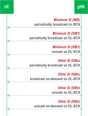
System Information (SI) consists of a MIB and a number of SIBs, which are divided into Minimum SI and Other SI:
-
Minimum SI comprises basic information required for initial access and information for acquiring any other SI. Minimum SI consists of:
- MIB contains cell barred status information and essential physical layer information of the cell required to receive further system information, e.g. CORESET#0 configuration. MIB is periodically broadcast on BCH.
- SIB1 defines the scheduling of other system information blocks and contains information required for initial access. SIB1 is also referred to as Remaining Minimum SI (RMSI) and is periodically broadcast on DL-SCH or sent in a dedicated manner on DL-SCH to UEs in RRC_CONNECTED.
-
Other SI encompasses all SIBs not broadcast in the Minimum SI. Those SIBs can either be periodically broadcast on DL-SCH, broadcast on-demand on DL-SCH (i.e. upon request from UEs in RRC_IDLE, RRC_INACTIVE, or RRC_CONNECTED), or sent in a dedicated manner on DL-SCH to UEs in RRC_CONNECTED (i.e., upon request, if configured by the network, from UEs in RRC_CONNECTED or when the UE has an active BWP with no common search space configured or when the UE configured with inter cell beam management is receiving DL-SCH from a TRP with PCI different from serving cell's PCI). Other SI consists of:
- SIB2 contains cell re-selection information, mainly related to the serving cell;
- SIB3 contains information about the serving frequency and intra-frequency neighbouring cells relevant for cell re-selection (including cell re-selection parameters common for a frequency as well as cell specific re-selection parameters);
- SIB4 contains information about other NR frequencies and inter-frequency neighbouring cells relevant for cell re-selection (including cell re-selection parameters common for a frequency as well as cell specific re-selection parameters), which can also be used for NR idle/inactive measurements;
- SIB5 contains information about E-UTRA frequencies and E-UTRA neighbouring cells relevant for cell re-selection (including cell re-selection parameters common for a frequency as well as cell specific re-selection parameters);
- SIB6 contains an ETWS primary notification;
- SIB7 contains an ETWS secondary notification;
- SIB8 contains a CMAS warning notification;
- SIB9 contains information related to GPS time and Coordinated Universal Time (UTC);
- SIB10 contains the Human-Readable Network Names (HRNN) of the NPNs listed in SIB1;
- SIB11 contains information related to idle/inactive measurements;
- SIB15 contains information related to disaster roaming;
- SIB16 contains slice-based cell reselection information;
- SIB17 and SIB17bis contain information related to TRS configuration for UEs in RRC_IDLE/RRC_INACTIVE;
- SIBpos contains positioning assistance data as defined in TS 37.355 and TS 38.331;
- SIB18 contains information related to the Group IDs for Network selection (GINs) associated with SNPNs listed in SIB1.
- SIB19 in TN contains NTN-specific parameters for NTN neighbour cells as defined in TS 38.331.
- SIB12 contains information related to NR sidelink communication;
- SIB13 contains information related to SystemInformationBlockType21 for V2X sidelink communication as specified in clause 5.2.2.28 of TS 36.331;
- SIB14 contains information related to SystemInformationBlockType26 for V2X sidelink communication as specified in clause 5.2.2.33 of TS 36.331;
- SIB23 contains information related to ranging and sidelink positioning;
- SIB25 contains TN coverage are information as defined in TS 38.331.
- SIB19 contains NTN-specific parameters for serving cell and optionally NTN-specific parameters for neighbour cells as defined in TS 38.331.
- SIB20 contains MCCH configuration;
- SIB21 contains information related to service continuity for MBS broadcast reception.
- SIB24 contains the information required to acquire the multicast MCCH/MTCH configuration as defined in TS 38.331.
- SIB22 contains ATG-specific parameters for serving cell and optionally ATG-specific parameters for neighbour cells as defined in TS 38.331.
For a cell/frequency that is considered for camping by the UE, the UE is not required to acquire the contents of the minimum SI of that cell/frequency from another cell/frequency layer. This does not preclude the case that the UE applies stored SI from previously visited cell(s).
If the UE cannot determine the full contents of the minimum SI of a cell by receiving from that cell, the UE shall consider that cell as barred.
In case of BA, the UE only acquires SI on the active BWP.
If the UE is configured with inter cell beam management:
- the UE is not required to acquire the SI from the serving cell while it is receiving DL-SCH from a TRP with PCI different from serving cell's PCI.
7.3.2 Scheduling p. 69
The MIB is mapped on the BCCH and carried on BCH while all other SI messages are mapped on the BCCH, where they are dynamically carried on DL-SCH. The scheduling of SI messages part of Other SI is indicated by SIB1.
For UEs in RRC_IDLE and RRC_INACTIVE while SDT procedure is not ongoing (see clause 18), a request for Other SI triggers a random access procedure (see clause 9.2.6) where MSG3 includes the SI request message unless the requested SI is associated to a subset of the PRACH resources, in which case MSG1 is used for indication of the requested Other SI. When MSG1 is used, the minimum granularity of the request is one SI message (i.e. a set of SIBs), one RACH preamble and/or PRACH resource can be used to request multiple SI messages and the gNB acknowledges the request in MSG2. When MSG 3 is used, the gNB acknowledges the request in MSG4.
For UEs in RRC_CONNECTED, a request for Other SI may be sent to the network, if configured by the network, in a dedicated manner (i.e., via UL-DCCH) and the granularity of the request is one SIB. The gNB may respond with an RRCReconfiguration including the requested SIB(s). It is a network choice to decide which requested SIBs are delivered in a dedicated or broadcasted manner.
The Other SI may be broadcast at a configurable periodicity and for a certain duration. The Other SI may also be broadcast when it is requested by UE in RRC_IDLE/RRC_INACTIVE/RRC_CONNECTED.
For a UE to be allowed to camp on a cell it must have acquired the contents of the Minimum SI from that cell. There may be cells in the system that do not broadcast the Minimum SI and where the UE therefore cannot camp.
7.3.3 SI Modification p. 69
Change of system information (other than for ETWS/CMAS, see clause 16.4) only occurs at specific radio frames, i.e. the concept of a modification period is used. System information may be transmitted a number of times with the same content within a modification period, as defined by its scheduling. The modification period is configured by system information.
When the network changes (some of the) system information, it first notifies the UEs about this change, i.e. this may be done throughout a modification period. In the next modification period, the network transmits the updated system information. Upon receiving a change notification, the UE acquires the new system information from the start of the next modification period. The UE applies the previously acquired system information until the UE acquires the new system information.
7.4 Access Control p. 70
NG-RAN supports overload and access control functionality such as RACH back off, RRC Connection Reject, RRC Connection Release and UE based access barring mechanisms.
One unified access control framework as specified in TS 22.261 applies to all UE states (RRC_IDLE, RRC_INACTIVE and RRC_CONNECTED) for NR. NG-RAN broadcasts barring control information associated with Access Categories and Access Identities (in case of network sharing, the barring control information can be set individually for each PLMN). The UE determines whether an access attempt is authorized based on the barring information broadcast for the selected PLMN, and the selected Access Category and Access Identity(ies) for the access attempt:
- For NAS triggered requests, NAS determines the Access Category and Access Identity(ies);
- For AS triggered requests, RRC determines the Access Category while NAS determines the Access Identity(ies).
7.5 UE Capability Retrieval framework p. 70
The UE reports its UE radio access capabilities which are static at least when the network requests. The gNB can request what capabilities for the UE to report based on band information. The UE capability can be represented by a capability ID, which may be exchanged in NAS signalling over the air and in network signalling instead of the UE capability structure.
In IAB, it is optional for an IAB-MT to support UE capability Retrieval framework and the related signalling. In case IAB-MT does not support UE capability Retrieval framework, IAB-MT capabilities are assumed to be known to the network by other means, e.g. OAM.
7.6 Transport of NAS Messages p. 70
NR provides reliable in-sequence delivery of NAS messages over SRBs in RRC, except at handover where losses or duplication can occur when PDCP is re-established. In RRC, NAS messages are sent in transparent containers. Piggybacking of NAS messages can occur in the following scenarios:
- At bearer establishment/modification/release in the DL;
- For transferring the initial NAS message during connection setup and connection resume in the UL.
7.7 Carrier Aggregation p. 71
When CA is configured, the UE only has one RRC connection with the network. At RRC connection establishment/re-establishment/handover, one serving cell provides the NAS mobility information, and at RRC connection re-establishment/handover, one serving cell provides the security input. This cell is referred to as the Primary Cell (PCell). Depending on UE capabilities, Secondary Cells (SCells) can be configured to form together with the PCell a set of serving cells. The configured set of serving cells for a UE therefore always consists of one PCell and one or more SCells.
The reconfiguration, addition and removal of SCells can be performed by RRC. At intra-NR handover and during connection resume from RRC_INACTIVE, the network can also add, remove, keep, or reconfigure SCells for usage with the target PCell. When adding a new SCell, dedicated RRC signalling is used for sending all required system information of the SCell i.e. while in connected mode, UEs need not acquire broadcast system information directly from the SCells.
7.8 Bandwidth Adaptation p. 71
To enable BA on the PCell, the gNB configures the UE with UL and DL BWP(s). To enable BA on SCells in case of CA, the gNB configures the UE with DL BWP(s) at least (i.e. there may be none in the UL). For the PCell, the BWP used for initial access is configured via system information. For the SCell(s), the BWP used after initial activation is configured via dedicated RRC signalling.
In paired spectrum, DL and UL can switch BWP independently. In unpaired spectrum, DL and UL switch BWP simultaneously. Switching between configured BWPs happens by means of RRC signalling, DCI, inactivity timer or upon initiation of random access. When an inactivity timer is configured for a serving cell, the expiry of the inactivity timer associated to that cell switches the active BWP to a default BWP configured by the network. There can be at most one active BWP per cell, except when the serving cell is configured with SUL, in which case there can be at most one on each UL carrier.
7.9 UE Assistance Information p. 71
When configured to do so, the UE can signal the network through UEAssistanceInformation:
- If it prefers an adjustment in the connected mode DRX cycle length, for the purpose of delay budget reporting;
- If it is experiencing internal overheating;
- If it prefers certain DRX parameter values, and/or a reduced maximum number of secondary component carriers, and/or a reduced maximum aggregated bandwidth and/or a reduced maximum number of MIMO layers and/or minimum scheduling offsets K0 and K2 for power saving purpose;
- If it expects not to send or receive any more data in the near future, and in this case, it can provide its preference to transition out of RRC_CONNECTED where this indication may express its preferred RRC state, or alternately, it may cancel an earlier indicated preference to transition out of RRC_CONNECTED;
- If it prefers (not) to be provisioned with reference time information;
- If it prefers to transition out of RRC_CONNECTED state for MUSIM operation and its preferred RRC state after transition;
- If it wants to include assistance information for setup or release of MUSIM gaps, and/or for setup the priority of periodic MUSIM gaps, and/or for keeping the collided MUSIM gaps;
- If it prefers to restrict UE capability temporarily or remove the restriction for MUSIM operation;
-
When affected by IDC problems that it cannot solve by itself:
- The list of frequencies affected by IDC problems (see clause 23.4 of TS 36.300);
- The list of frequency ranges/frequency range combinations affected by the IDC problems;
- DRX based TDM assistance information (see clause 23.4.2 of TS 36.300);
- Its RRM measurement relaxation status indicating whether RRM measurement relaxation criteria are met or not;
- Its RLM measurement relaxation status indicating whether the UE is applying RLM measurements relaxation;
- Its BFD measurement relaxation status indicating whether the UE is applying BFD measurements relaxation;
- If it prefers not operating on multi-Rx (i.e. not supporting simultaneous reception with different QCL-typeD) for FR2.
7.10 Segmentation of RRC messages |R16| p. 72
An RRC message may be segmented in case the size of the encoded RRC message PDU exceeds the maximum PDCP SDU size. Segmentation is performed in the RRC layer using a separate RRC PDU to carry each segment. The receiver reassembles the segments to form the complete RRC message. All segments of an RRC message are transmitted before sending another RRC message. Segmentation is supported in both uplink and downlink as specified in TS 38.331.
![]()
![]()
![]()