Content for TS 23.280 Word version: 19.2.0
1…
5…
5.2.8…
6
7…
7.3.2
7.4…
7.4.3…
7.5…
8…
9…
9.2.2…
9.2.2.2…
9.3…
10…
10.1.2…
10.1.3…
10.1.4.3…
10.1.4.5…
10.1.5…
10.1.6…
10.2…
10.2.3…
10.2.4.2…
10.2.4.3…
10.2.5…
10.2.7…
10.3…
10.6…
10.7…
10.7.3…
10.7.3.4…
10.7.3.7…
10.7.3.7.3
10.7.3.8…
10.7.3.10…
10.8…
10.8.4…
10.8.5…
10.9…
10.9.3…
10.9.3.5…
10.9.3.8…
10.9.3.9…
10.9.3.9.3…
10.9.3.9.4…
10.9.3.10…
10.9.3.10.4…
10.9.3.10.6…
10.10…
10.10.1.2.3…
10.10.2…
10.10.3…
10.10.3.3…
10.10.3.4…
10.11…
10.11.5…
10.12…
10.13…
10.13.3…
10.13.7…
10.13.10…
10.14…
10.15…
10.15.3…
10.15.3.3…
10.15.3.4…
10.16…
10.17…
10.17.3…
10.17.5…
11…
11.3…
11.5…
11.5.2…
11.5.3…
11.5.3.3.2A…
11.5.4…
A…
B…
C…
10.7.3.10 MBMS bearer event notification
10.7.3.11 Use of FEC to protect MBMS transmissions
10.7.3.11.1 General
10.7.3.11.2 FEC encoding by the BM-SC
10.7.3.11.3 FEC encoding by the MC service server
10.7.3.12 Header compression over MBMS with ROHC
10.7.3.12.1 General
10.7.3.12.2 Header compression by the MC service server
10.7.3.12.3 Header compression by the BM-SC
10.7.3.13 Use of MBMS bearer for group status
...
...
10.7.3.10 MBMS bearer event notification |R15| p. 154
10.7.3.10.1 General p. 154
The MC service server is an instantiation of a GCS AS. For the MC service server to know the status of the MBMS bearer, and thus know the networks ability to deliver the service, it is required that the network provides MBMS bearer event notifications to the MC service server. The different events notified to the MC service server include the MBMS bearer start result (e.g. when the first cell successfully allocated MBMS resources), including information if any cells fail to allocate MBMS resources to a specific MBMS bearer, the current status of the MBMS bearer, MBMS bearer suspension/resume or overload scenarios.
10.7.3.10.2 Procedure p. 155
The procedure in Figure 10.7.3.10.2-1 shows notification information flows from MC service server to BM-SC.
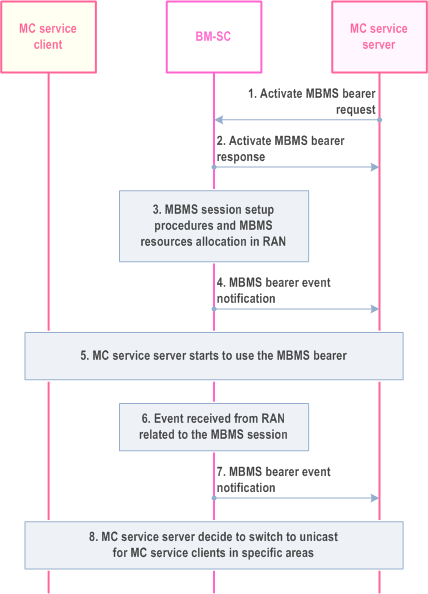
Step 1.
The MC service server activates an MBMS bearer. The activation of the MBMS bearer is done on the MB2-C reference point and according to TS 23.468.
Step 2.
The BMSC will respond to the activation with an Activate MBMS bearer response message, according to TS 23.468.
Step 3.
The EPC and RAN will initiate the MBMS session start procedure according to TS 23.246. This procedure is outside the scope of this specification.
Step 4.
At the first indication of a successful MBMS session start procedure, the BM-SC sends a MBMS bearer event notification, indicating that the MBMS bearer is ready to use.
Step 5.
The MC service server starts to use the MBMS bearer according to the MBMS procedures in this specification.
Step 6.
An event from RAN related to the MBMS session is received by the BM-SC.
Step 7.
The BM-SC notifies the MC service server of certain MBMS related events including references to affected MBMS services areas or list of cells. Example of such events may be radio resources not available, overload, MBMS suspension.
Step 8.
The MC service server may decide, based on the received events, to switch to unicast transmission for relevant MC service clients.
10.7.3.11 Use of FEC to protect MBMS transmissions |R15| p. 156
10.7.3.11.1 General p. 156
Application layer FEC can be used to recover the packet losses when delivering a MC service over MBMS, to reach its required level of QoS.
Support of FEC is optional for the MC service servers and MC service clients
Adding FEC introduces an extra latency in the end to end media transport. This extra latency is bounded to fulfil the low latency requirements for mission critical services.
FEC can be applied by the BM-SC if required by the MC service server (subclause 10.7.3.11.2), or directly by the MC service server (subclause 10.7.3.11.3). FEC is decoded by the MC service client. Either method is independent of the other.
The MC service server may consider the listening status reports from previous MBMS bearer quality detection procedures (subclause 10.7.3.6) to adjust the FEC parameters when delivering over a new MBMS bearer.
10.7.3.11.2 FEC encoding by the BM-SC p. 156
In this procedure, depicted in Figure 10.7.3.11.2-1, the MC service server asks the BM-SC to apply FEC to a set of medias, transported by a MBMS bearer, using the Setup FEC request.
This procedure can be applied when using pre-established MBMS bearers (10.7.3.1) or dynamic MBMS bearers (10.7.3.2).
Pre-condition:
- The MC service server has already activated a MBMS Bearer, with the MBMS Bearer request specified in TS 23.468.
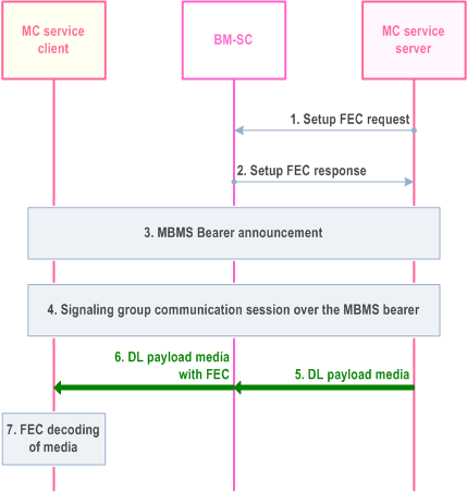
Step 1.
The MC service server decides to set up FEC for a set of MC service media flows. The request is done on the MB2-C reference point. It includes the following elements: the TMGI of the bearer transporting those media, the media descriptions (codecs, transport protocols, bitrates, destination ip addresses and ports), the identification of the FEC repair packet flow (IP destination and port), an upper bound to the additional latency resulting to FEC application. The MC Service server may perform this request several times to protect separately different sets of media transported within the same MBMS bearer.
Step 2.
If the BM-SC can satisfy the request, the Setup FEC response includes a modified list of media information and FEC information. The response also includes an identifier to the FEC process instance, which can be used to release the application of FEC for these media flows.
Step 3.
The MC service server announces the MBMS bearer to the MC service client with the MBMS bearer announcement procedure, including the modified list of medias information and FEC information within the SDP information.
Step 4.
When the MC service server decides to transmit the MC service media flow for a group communication, the MC service server sends to the group a message identifying the MC service media flow and the TMGI of the MBMS bearer, such as the MapGroupToBearer message for MCPTT, specified in TS 23.379, or the MapGroupToBearer message for MCVideo, specified in TS 23.380.
Step 5.
The MC service server sends the downlink media to the BM-SC on the MB2-U reference points and according to TS 23.468.
Step 6.
The BM-SC performs FEC encoding of the downlink media in accordance to the announced FEC algorithm and parameters and delivers it over MBMS.
Step 7.
The MC service client performs FEC decoding of the encoded media flows in accordance to the announced FEC information and delivers the decoded flows to the media player.
10.7.3.11.3 FEC encoding by the MC service server p. 157
In this procedure, depicted in Figure 10.7.3.11.3-1, FEC encoding is performed by the MC service server. The MC service server includes the FEC information within the MBMS bearer announcement. The FEC decoding is performed by the MC service client.
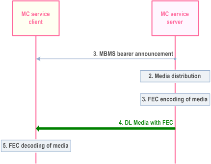
Step 1.
The MC service server sends MBMS bearer announcement message with FEC information to the MC service clients.
Step 2.
As media packets arrive from the originating MC service UE (not shown in diagram), the media is processed by the media distribution function on the MC service server.
Step 3.
The MC service server performs FEC encoding and processing in accordance with the selected FEC algorithm.
Step 4.
The MC service server sends the media with FEC to the MC service client (both payload source packets and the FEC repair packets are sent on the MB2-U to the BM-SC, which transparently forwards them unmodified to the MC service client).
Step 5.
MC service client performs FEC decoding and processing in accordance with the selected FEC algorithm
10.7.3.12 Header compression over MBMS with ROHC |R15| p. 158
10.7.3.12.1 General p. 158
Support of ROHC over MBMS is optional for the MC service servers and MC service clients. If header compression and FEC are both applied to a communication over MBMS, the header compression shall be performed after the FEC encoding.
These procedures can be applied when using pre-established MBMS bearers (see clause 10.7.3.1) or dynamic MBMS bearers (see clause 10.7.3.2).
10.7.3.12.2 Header compression by the MC service server p. 158
In this procedure, depicted in Figure 10.7.3.12.2-1, header compression is performed by the MC service server. The MC service server includes the ROHC information within the MBMS bearer announcement. The header decompression is performed by the MC service client.
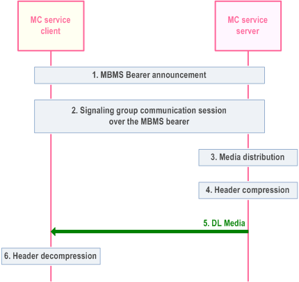
Step 1.
The MC service server sends MBMS bearer announcement message with ROHC information to the MC service clients. The ROHC information contains the list of ROHC profiles and the ROHC context identifier range).
Step 2.
When the MC service server decides to transmit the MC service media flow for a group communication, the MC service server sends to the group a message identifying the MC service media flow and the TMGI of the MBMS bearer, such as the MapGroupToBearer message for MCPTT, specified in TS 23.379, or the MapGroupToBearer message for MCVideo, specified in TS 23.281.
Step 3.
As media packets arrive from the originating MC service UE (not shown in diagram), the media is processed by the media distribution function on the MC service server.
Step 4.
The MC service server performs header compression in accordance with the ROHC information.
Step 5.
The MC service server sends the header compressed media to the MC service client
Step 6.
The MC service client performs header decompression in accordance to the ROHC information
10.7.3.12.3 Header compression by the BM-SC p. 159
In this procedure, depicted in Figure 10.7.3.12.3-1, the MC service server asks the BM-SC to compress headers for a set of medias, transported by a MBMS bearer, using the Setup ROHC request.
Pre-condition:
- The MC service server has already activated a MBMS Bearer, with the MBMS Bearer request specified in TS 23.468.
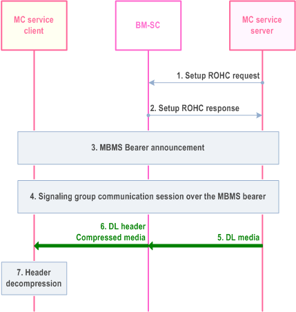
Step 1.
The MC service server decides to set up ROHC within a MBMS bearer. The request is done on the MB2-C reference point. It includes the following elements: the ROHC configuration, the list of RTP and UDP flows to be header compressed, characterized by their destination IPs and port numbers. For each of these flows, the request may indicate a target periodicity for the full header packets.
Step 2.
If the BM-SC can satisfy the request, the Setup ROHC response confirm the application of header compression.
Step 3.
The MC service server announces the MBMS bearer to the MC service client with the MBMS bearer announcement procedure, including the ROHC information.
Step 4.
When the MC service server decides to transmit the MC service media flow for a group communication, the MC service server sends to the group a message identifying the MC service media flow and the TMGI of the MBMS bearer, such as the MapGroupToBearer message for MCPTT, specified in TS 23.379, or the MapGroupToBearer message for MCVideo, specified in TS 23.281.
Step 5.
The MC service server sends the downlink media to the BM-SC on the MB2-U reference points and according to TS 23.468.
Step 6.
The BM-SC compresses headers of the downlink media in accordance to the announced ROHC parameters and delivers it over MBMS.
Step 7.
The MC service client performs header decompression in accordance to the ROHC information.
10.7.3.13 Use of MBMS bearer for group status |R16| p. 160
The MC service server, e.g., MCPTT server, may use the MBMS bearer to inform the status of a group communication (indicating the group call is on-going or not) when the group call is set up on unicast bearers. The affiliated clients that will perform late entry chat group calls or rejoin calls may use this group status information to decide whether to join the calls. The information flows for group status notification are specified in subclause 10.7.2.12.