Content for TS 23.280 Word version: 19.4.0
1…
5…
6
7…
8…
9…
10…
10.1.5…
10.2…
10.2.6…
10.3…
10.6…
10.7…
10.7.3.8…
10.8…
10.9…
10.9.3.9…
10.10…
10.10.3
10.11…
10.12…
10.13…
10.14…
10.15…
10.16…
10.17…
11…
11.5…
A…
B…
C…
E…
C Application Priority
C.1 Use of application priorities
D Considerations for MC gateway UE selection
D.1 General
D.2 Potential operating Conditions
C Application Priority |R17| p. 379
C.1 Use of application priorities p. 379
Different communications between two or more MC service users need to be distinguished in their urgency in order to appropriately or less preferably allocate 3GPP system transport resources. Also simultaneous incoming communications to a MC service user requires an indication of the urgency in order to preferentially join the communication in accordance with the urgency.
To make this distinction of urgencies, the MC system necessarily supports different types of priorities and corresponding levels within each priority category representing the relative importance of a request at the application level. The use of application priority allows the MC system to decide whether a communication establishment or modification request can be accepted or needs to be rejected (e.g. in case of transport resource limitations), or it allows the MC service client to rank simultaneous incoming communication for presentation to an MC service user. Hence the application priority can also be used to decide which existing transport resources (e.g. bearers) to pre-empt during resource limitations. Such pre-emption capability information defines whether a communication can obtain transport resources that were already assigned to another communication with a lower priority level. The pre-emption vulnerability information defines whether a communication can lose the resources assigned to it in order to admit a communication with higher priority level.
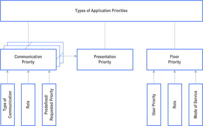
The following types of application priorities are provided by the MC system:

Communication priority involves a combination of the type of call/communication, the role of the requesting MC service user, and the predefined/requested priority of the initiating MC service user and/or group.
Presentation priority involves the determination of which communications, from within multiple simultaneous possible, are the highest priority to present to the MC service user either audibly or visibly. An example would be a private call received at the same time as an emergency call on a monitored group. This category can be configured uniquely for each MC service user.
Floor priority involves the determination of who can transmit within a communication at a particular time. This is essentially the priority of the MC service user according to its profile, and possibly modified by its role and/or mode of service (e.g. using emergency or imminent peril call). This category is used, for example, to determine the ordering of the floor control queue within an established communication.
D Considerations for MC gateway UE selection |R18| p. 381
D.1 General p. 381
Operating conditions can influence the selection and the use of the MC gateway.
Multiple conditions can be considered by the non-3GPP device either to connect to another MC gateway UE (e.g. with better operating conditions for the requested service), or to re-connect to the same MC gateway UE (e.g. reattempt connection after a certain time).
D.2 Potential operating Conditions p. 381
Possible operating conditions information could belong to one of the following categories:
MC gateway UE capacity limits
The MC gateway UE might not be able to allow non-3GPP devices to connect when the limit of connected MC clients has been reached.
3GPP access congestion
The MC gateway UE can make use of to the special Categories/Access Identity, the preferential access applies based on its assigned Access Control Class/Access Identity during periods of congestion. The MC gateway UE subscription allows to obtain priority treatment for the required communication.
Nevertheless, the serving access network can indicate to the UEs (including MC gateway UE) that Access Class Barring applies and this can be passed by the MC gateway UE to the non-3GPP device.
PLMN reselection
PLMN reselection depends on operator policy, roaming agreements, and on national/regional regulatory requirements.
Network status information
If the network status information of an EPS/5GS capability available at MC gateway UE, it can be further propagated to the corresponding non-3GPP devices for further processing (e.g., if the requested QoS for service can be provided for MC client or not).