Content for TS 23.280 Word version: 19.2.0
1…
5…
5.2.8…
6
7…
7.3.2
7.4…
7.4.3…
7.5…
8…
9…
9.2.2…
9.2.2.2…
9.3…
10…
10.1.2…
10.1.3…
10.1.4.3…
10.1.4.5…
10.1.5…
10.1.6…
10.2…
10.2.3…
10.2.4.2…
10.2.4.3…
10.2.5…
10.2.7…
10.3…
10.6…
10.7…
10.7.3…
10.7.3.4…
10.7.3.7…
10.7.3.7.3
10.7.3.8…
10.7.3.10…
10.8…
10.8.4…
10.8.5…
10.9…
10.9.3…
10.9.3.5…
10.9.3.8…
10.9.3.9…
10.9.3.9.3…
10.9.3.9.4…
10.9.3.10…
10.9.3.10.4…
10.9.3.10.6…
10.10…
10.10.1.2.3…
10.10.2…
10.10.3…
10.10.3.3…
10.10.3.4…
10.11…
10.11.5…
10.12…
10.13…
10.13.3…
10.13.7…
10.13.10…
10.14…
10.15…
10.15.3…
10.15.3.3…
10.15.3.4…
10.16…
10.17…
10.17.3…
10.17.5…
11…
11.3…
11.5…
11.5.2…
11.5.3…
11.5.3.3.2A…
11.5.4…
A…
B…
C…
11.5.4 Disconnection mechanism
11.5.4.1 General
11.5.4.2 Disconnection for non-3GPP devices that host an MC client
11.5.4.2.1 General
11.5.4.2.2 Information flows
11.5.4.2.2.1 Disconnection request
11.5.4.2.2.2 Disconnection response
11.5.4.2.2.3 Connection status notification
11.5.4.2.3 Disconnection procedure
11.5.4.2.4 Connection status notification
11.5.4.3 Disconnection for non-3GPP devices that do not host an MC client
11.5.4.3.1 General
11.5.4.3.2 Information flows
11.5.4.3.2.1 Disconnection request
11.5.4.3.2.2 Disconnection response
11.5.4.3.3 Disconnection procedure
...
...
11.5.4 Disconnection mechanism p. 358
11.5.4.1 General p. 358
A connection using an MC gateway UE by the corresponding MC gateway client can be cancelled over time or re-established using same or another MC gateway UE. The connection/ disconnection mechanism allows the MC gateway client to disconnect the use of the corresponding MC gateway UE considering the various MC client hosting scenarios.
Under certain circumstances, the connection with the corresponding MC gateway UE can change or has to be adjusted. The various reasons are detailed in the informative Annex D. For this purpose, the MC gateway UE can send a notification to the corresponding MC gateway client hosted on a non-3GPP device.
11.5.4.2 Disconnection for non-3GPP devices that host an MC client p. 359
11.5.4.2.1 General p. 359
The clause is applied to non-3GPP devices which can host an MC client. The MC gateway UE forwards the disconnection request to the corresponding MC server to disconnect the MC gateway UE to MC client connection.
11.5.4.2.2 Information flows p. 359
11.5.4.2.2.1 Disconnection request p. 359
Table 11.5.4.2.2.1-1 describes the information flow disconnection request sent from the MC client, which resides on a non-3GPP device, to the corresponding MC server via the MC gateway UE.
| Information element | Status | Description |
|---|---|---|
| GW MC service ID | M | The GW MC service ID of the requesting MC service user. |
11.5.4.2.2.2 Disconnection response p. 359
Table 11.5.4.2.2.2-1 describes the information flow disconnection response sent from the MC server to the MC gateway UE, and from the MC gateway UE to the MC client residing on a non-3GPP device.
| Information element | Status | Description |
|---|---|---|
| GW MC service ID | M | The GW MC service ID of the requesting MC service user. |
| Response | M | Result of the disconnection request. |
11.5.4.2.2.3 Connection status notification p. 359
Table 11.5.4.2.2.3-1 describes the information flow connection status notification sent from the MC gateway UE to the MC client, which resides on a non-3GPP device.
| Information element | Status | Description |
|---|---|---|
| GW MC service ID | M | The GW MC service ID of the associated MC client. (see NOTE 1) |
| Status information | M | This information element provides connection status. (see NOTE 2). |
|
NOTE 1:
The GW MC service ID indicates for which MC service the connection is to be disconnected.
NOTE 2:
Information about the connection status are further detailed in Annex D.
|
||
11.5.4.2.3 Disconnection procedure p. 359
The procedure for disconnection via an MC gateway UE towards an MC server is shown in Figure 11.5.4.2.3-1.
Pre-conditions:
- The MC service user has an authorized connection via an MC gateway UE to an MC server.
- The MC clients have no communication ongoing, e.g. group communication.
- The MC gateway client service user on a non-3GPP device wishes to disconnect the authorized connection.
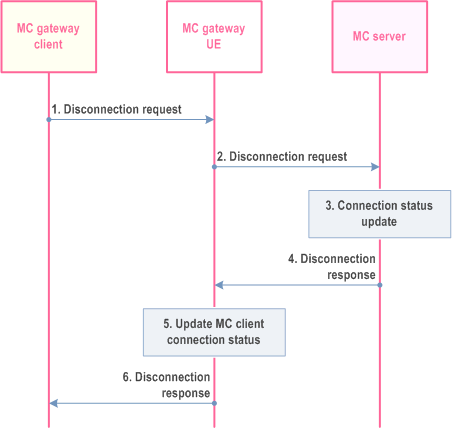
Step 1.
The MC gateway client requests disconnection via the MC gateway UE with an MC server. The MC gateway client of the MC service user provides the GW MC service ID.
Step 2.
The MC gateway UE sends the disconnection request to the MC server to disconnect the authorized connection between the MC gateway client and the MC server.
Step 3.
The MC server verifies if the connection is active and updates the connection status as disconnected.
Step 4.
The MC server sends the disconnection response to the MC gateway UE.
Step 5.
The MC gateway UE updates MC gateway client connection status as disconnected.
Step 6.
The MC gateway UE sends the disconnection response to the MC gateway client.
11.5.4.2.4 Connection status notification p. 360
The procedure for connection status notification initiated by an MC gateway UE towards an MC gateway client is shown in Figure 11.5.4.2.4-1 informs about the status of connection status that may result into a disconnection.
Pre-conditions:
- The MC gateway client has an authorized connection via an MC gateway UE to an MC server.
- The MC gateway UE is no longer able to provide the requested service depending on reasons further detailed in Annex D.
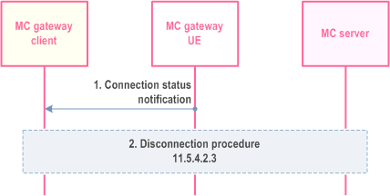
Step 1.
The MC gateway UE wants to disconnect the connection with an MC server for the corresponding MC gateway client. The MC gateway UE sends connection status notification to the MC gateway client using the corresponding GW MC gateway ID.
Step 2.
The connection status may result that the MC gateway client wants to disconnect the connection with the MC server (see disconnection in clause 11.5.4.2.3).
11.5.4.3 Disconnection for non-3GPP devices that do not host an MC client p. 361
11.5.4.3.1 General p. 361
The clause is applied to non-3GPP devices which cannot host an MC client. The MC server is requested to disconnect the MC gateway UE to MC client connection on demand.
11.5.4.3.2 Information flows p. 361
11.5.4.3.2.1 Disconnection request p. 361
Table 11.5.4.3.2.1-1 describes the information flow disconnection request sent from the MC client, which resides on a MC gateway UE, to the MC server.
| Information element | Status | Description |
|---|---|---|
| GW MC service ID | M | The GW MC service ID of the requesting MC service user. |
|
NOTE:
The GW MC service ID indicates for which MC service the connection is to be disconnected.
|
||
11.5.4.3.2.2 Disconnection response p. 361
Table 11.5.4.3.2.2-1 describes the information flow disconnection response sent from the MC server to the MC client residing on the MC gateway UE.
| Information element | Status | Description |
|---|---|---|
| GW MC service ID | M | The GW MC service ID of the requesting MC service user. |
| Result | M | Success or failure of the disconnection request (successful/failed; not permitted). |
11.5.4.3.3 Disconnection procedure p. 362
The procedure for disconnection of an MC gateway client hosted by the MC gateway UE towards an MC server is shown in Figure 11.5.4.3.3-1.
Pre-conditions:
- The MC service user has an authorized connection using an MC gateway UE to an MC server.
- The MC clients have no communication ongoing, e.g. group communication.
- The MC gateway client hosted on a MC gateway UE wishes to disconnect the authorized connection.
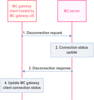
Step 1.
The MC gateway client, hosted by the MC gateway UE, sends a disconnection request to the corresponding MC server encompassing the GW MC service ID.
Step 2.
The MC server verifies if the connection is active and updates the connection status as disconnected.
Step 3.
The MC server sends the disconnection response to the MC gateway client residing on the MC gateway UE.
Step 4.
The MC gateway UE updates MC gateway client connection status to disconnected.
![]()
![]()
![]()