Content for TS 23.280 Word version: 19.2.0
1…
5…
5.2.8…
6
7…
7.3.2
7.4…
7.4.3…
7.5…
8…
9…
9.2.2…
9.2.2.2…
9.3…
10…
10.1.2…
10.1.3…
10.1.4.3…
10.1.4.5…
10.1.5…
10.1.6…
10.2…
10.2.3…
10.2.4.2…
10.2.4.3…
10.2.5…
10.2.7…
10.3…
10.6…
10.7…
10.7.3…
10.7.3.4…
10.7.3.7…
10.7.3.7.3
10.7.3.8…
10.7.3.10…
10.8…
10.8.4…
10.8.5…
10.9…
10.9.3…
10.9.3.5…
10.9.3.8…
10.9.3.9…
10.9.3.9.3…
10.9.3.9.4…
10.9.3.10…
10.9.3.10.4…
10.9.3.10.6…
10.10…
10.10.1.2.3…
10.10.2…
10.10.3…
10.10.3.3…
10.10.3.4…
10.11…
10.11.5…
10.12…
10.13…
10.13.3…
10.13.7…
10.13.10…
10.14…
10.15…
10.15.3…
10.15.3.3…
10.15.3.4…
10.16…
10.17…
10.17.3…
10.17.5…
11…
11.3…
11.5…
11.5.2…
11.5.3…
11.5.3.3.2A…
11.5.4…
A…
B…
C…
10.14 Generic procedures for interconnection
10.14.1 General
10.14.2 Generic call procedure with topology hiding
10.14.2.1 General
10.14.2.2 Procedure for calls with topology hiding
10.14.3 Generic call procedure for enforcement of local MC service group configuration
10.14.3.1 General
10.14.3.2 MC service group call initiated in the partner MC system of the MC service group
10.14.3.3 MC service group call request received from the primary MC system of the MC service group
10.14.4 Generic call procedure for media replication in participating MC system in MC service group calls
10.14.4.1 General
10.14.4.2 Media replication in the partner MC system of the MC service group
...
...
10.14 Generic procedures for interconnection |R15| p. 277
10.14.1 General p. 277
Interconnection provides a means for communication between different MC systems with differing levels of trust between those MC systems. This subclause describes generic procedures for interconnection which are variations of specific procedures detailed in TS 23.379 and TS 23.281. These procedures should be read in conjunction with specific procedures in those specifications.
10.14.2 Generic call procedure with topology hiding p. 277
10.14.2.1 General p. 277
The procedure in this subclause applies to MC service group calls and private calls made between multiple MC systems where topology hiding is required. An MC gateway server in an MC system is used to route calls to and from partner MC systems, and by doing so hides the topology of the MC system.
10.14.2.2 Procedure for calls with topology hiding p. 277
Figure 10.14.2.2-1 shows the procedure where an MC service client initiates an MC service group call to an MC service group where the primary MC system of that MC service group is an interconnected MC system, or where an MC service client initiates an MC service private call to an MC service user where the primary MC system of that MC service user is an interconnected partner MC system. In this procedure, both MC systems make use of topology hiding.
Pre-conditions:
- MC service client 1 is receiving MC service in a different MC system to the primary MC system of the target MC service group or MC service user, and the MC systems are interconnected.
- If the call to be originated by MC service client 1 is an MC service group call, MC service client 1 has affiliated to the MC service group.
- If the call to be originated by MC service client 1 is an MC service private call, the target MC service client, MC service client 2, is receiving service from the primary MC system of that MC service client.
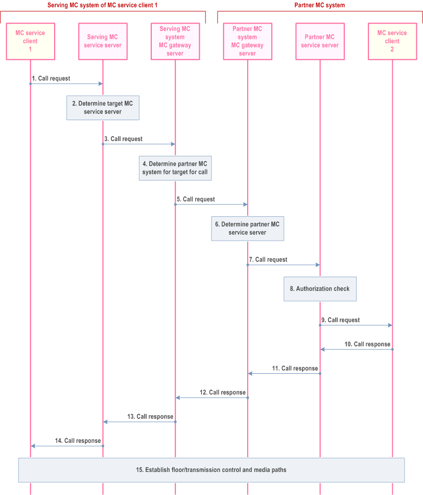
Step 1.
MC service client 1 initiates a call request to a target MC service user or MC service group, where the primary MC system of that MC service user or MC service group is an interconnected partner MC system.
Step 2.
The serving MC service server of MC service client 1 determines that the call has a target in a different MC system, and that the MC gateway server is the correct next hop for the call.
Step 3.
The serving MC service server of MC service client 1 forwards the call request to the MC gateway server of the serving MC system.
Step 4.
The MC gateway server identifies the correct partner MC system which is the primary MC system for the target of the call.
Step 5.
The MC gateway server of the primary MC system of MC service client 1 forwards the call request to the MC gateway server of the partner MC system.
Step 6.
The MC gateway server of the partner MC system determines the MC service server which is the primary MC service server for the target MC service user or MC service group.
Step 7.
The call request is forwarded to the partner MC service server which is the primary MC service server of the target MC service user or MC service group.
Step 8.
The partner MC service server which is the primary MC service server of the target MC service user or MC service group checks that the call is authorized to be made. The authorization process checks that the call origin is permissible (i.e. from the serving MC system of calling MC service user, and from that calling MC service user) for a call to the target MC service user or MC service group.
Step 9.
Providing that the authorization in step 8 is successful, the call request is sent to MC service client 2.
Step 10.
MC service client 2 sends a call response to the call request.
Step 11.
The partner MC service server, which is the primary MC service server of the target MC service user or MC service group, sends a call response to the MC gateway server in the partner MC system.
Step 12.
The MC gateway server in the partner MC system sends the call response to the MC gateway server in the primary MC system of MC service client 1.
Step 13.
The MC gateway server in the primary MC system sends the call response to the serving MC service server of MC service client 1.
Step 14.
The serving MC service server sends the call response to MC service client 1.
Step 15.
If the call response was successful, floor control and media paths are established for the call.
10.14.3 Generic call procedure for enforcement of local MC service group configuration p. 279
10.14.3.1 General p. 279
The procedure in the following subclauses apply to MC service group calls made between multiple MC systems where the partner MC system applies local configuration to the MC service group configuration which has been provided by the primary MC system of the MC service group. The serving MC server of the MC service group members, that is a participating server for the MC service group, applies enforcement of local MC service group configuration.
10.14.3.2 MC service group call initiated in the partner MC system of the MC service group p. 279
Figure 10.14.3.2-1 shows the procedure where an MC service group call is initiated by an MC service client receiving MC service in the partner MC system of the MC service group.
Pre-conditions:
- MC service client 1 is receiving MC service in a partner MC system of the MC service group, and the MC systems are interconnected.
- MC service client 1 has affiliated to the MC service group.
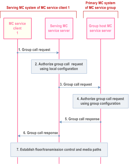
Step 1.
MC service client 1 initiates a group call request to the MC service group, where the primary MC system of that MC service group is an interconnected partner MC system.
Step 2.
The serving MC service server of MC service client 1 authorizes the group call request using local group configuration information.
Step 3.
If the group call request authorization by the serving MC service server of MC service client 1 is successful, the serving MC service server forwards the group call request to the group host MC service server in the primary MC system of the MC service group.
Step 4.
The primary MC service server of the MC service group checks that the call is authorized to be made. The authorization process checks that the call origin is permissible (i.e. from the serving MC system of calling MC service user, and from that calling MC service user) for a call to that MC service group.
Step 5.
Providing that authorization in step 4 is successful, the group call response is sent to the serving MC service server of MC service client 1.
Step 6.
The serving MC service server sends the MC service group call response to MC service client 1.
Step 7.
Floor control or transmission control and media paths are established for the MC service group call.
10.14.3.3 MC service group call request received from the primary MC system of the MC service group p. 280
Figure 10.14.3.3-1 shows the procedure where an MC service group call request is received from the primary MC system of the MC service group, which includes an MC service group member MC service client 1 that is receiving service within the partner MC system of the MC service group. Any topology hiding by the primary or partner MC system of the MC service group is not shown within this procedure.
Pre-conditions:
- MC service client 1 is receiving MC service in a partner MC system of the MC service group, and the MC systems are interconnected.
- MC service client 1 has affiliated to the MC service group.
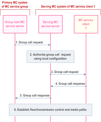
Step 1.
A group call request is received from the group host MC service server in the primary MC system of the MC service group.
Step 2.
The serving MC service server of MC service client 1 authorizes the group call request using local group configuration information.
Step 3.
If the group call request authorization by the serving MC service server of MC service client 1 is successful, the serving MC service server sends the group call request to MC service client 1.
Step 4.
MC service client 1 responds to the group call request with a group call response.
Step 5.
The group call response is sent to the group host MC service server of the MC service group.
Step 6.
Floor control or transmission control and media paths are established for the MC service group call.
10.14.4 Generic call procedure for media replication in participating MC system in MC service group calls p. 281
10.14.4.1 General p. 281
The procedure in the following subclause applies to MC service group calls made between multiple MC systems where the partner MC system carries out media replication to served MC service group members.
10.14.4.2 Media replication in the partner MC system of the MC service group p. 281
Figure 10.14.4.2-1 shows the procedure where an MC service group call is initiated by an MC service client receiving MC service in the primary MC system of the MC service group, and media replication takes place in the partner MC system.
Pre-conditions:
- MC service client 1 is receiving MC service in the primary MC system of the MC service group, and the MC systems are interconnected.
- MC service clients 2, 3 and n are receiving MC service in the partner MC system of the MC service group.
- MC service clients 1, 2, 3 and n have affiliated to the MC service group.
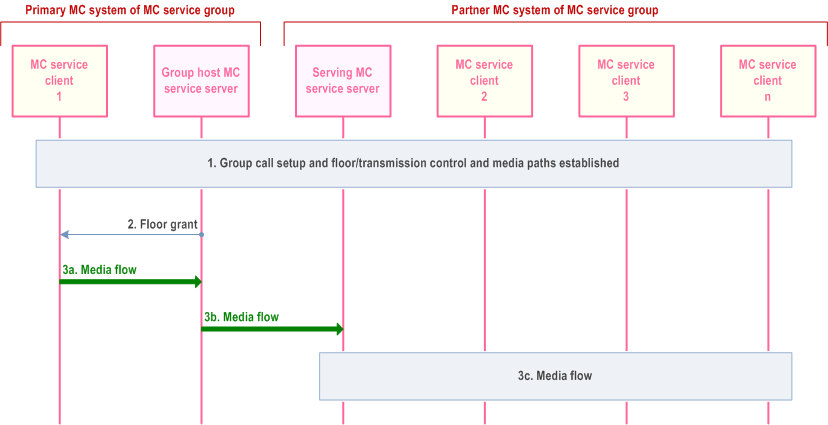
Step 1.
An MC service group call is set up and floor or transmission control and media paths are established, and MC service client 1 requests permission to transmit media to the MC service group.
Step 2.
The group host MC service server grants the requested floor or transmission permission to MC service client 1.
Step 3a.
MC service client 1 transmits a media stream to the group host MC service server.
Step 3b.
The group host MC service server sends a single media stream to the serving MC service server of MC service clients 2, 3 and n in the partner MC system of the MC service group.
Step 3c.
The serving MC service server of MC service clients 2, 3 and n replicates and distributes the media to MC service clients 2, 3 and n.
![]()
![]()
![]()