Content for TS 38.401 Word version: 18.2.0
1…
5…
6…
6.1.4
6.1.5…
6.2…
7…
8…
8.2…
8.2.1.4…
8.2.2…
8.2.3…
8.2.4
8.2.5
8.3…
8.4…
8.4.4…
8.5…
8.9…
8.9.4…
8.9.6…
8.9.7…
8.10
8.11…
8.12…
8.13…
8.14…
8.15…
8.15.2…
8.16…
8.17…
8.17.3…
8.17.4
8.18…
8.19…
8.19.2
8.19.3
8.19.4…
8.21…
8.22…
8.23…
8.24…
9…
A…
9 Synchronization
9.1 gNB Synchronization
10 NG-RAN interfaces
10.1 NG interface
10.2 Xn interface
10.3 F1 interface
10.4 E1 interface
10.5 Antenna interface - general principles
11 Overall procedures in NG-RAN Architecure
11.1 Multiple TNLAs for Xn-C
9 Synchronization p. 152
9.1 gNB Synchronization p. 152
The gNB shall support a logical synchronization port for phase-, time- and/or frequency synchronization.
Logical synchronization port for phase- and time-synchronization shall provide:
- accuracy that allows to meet the gNB requirements on maximum relative phase difference for all gNBs in synchronized TDD-unicast area;
- continuous time without leap seconds traceable to common time reference for all gNBs in synchronized TDD-unicast area. In the case the TDD-unicast area is not isolated, the common time reference shall be traceable to the Coordinated Universal Time (UTC).
SFN = {time}mod{period(SFN)},
where:
time
In case gNB is connected via TDM interface, it may be used to frequency synchronize the gNB. The characteristics of the clock in the gNB shall be designed taking into account that the jitter and wander performance requirements on the interface are in accordance with network limits for output wander at traffic interfaces of either ITU-T Recommendation G.823 [8], ITU-T Recommendation G.824 [9] or network limits for the maximum output jitter and wander at any hierarchical interface of ITU-T Recommendation G.825 [10], whichever is applicable.
In case gNB is connected via Ethernet interface and the network supports Synchronous Ethernet, the gNB may use this interface to get frequency synchronization. In this case the design of the gNB clock should be done considering the jitter and wander performance requirements on the interface are as specified for output jitter and wander at EEC interfaces of ITU-T Recommendation G.8261/Y.1361 [11], defined in clause 9.2.1. Further considerations on Synchronous Ethernet recommendations and architectural aspects are defined in clause 12.2.1 and Annex A of ITU-T Recommendation G.8261/Y.1361 [11].
A configurable LTE TDD-offset of start frame shall be supported by all gNBs in synchronized TDD-unicast areas in order to achieve interoperability in coexistence scenarios.
time adjusted by the common SFN initialization time, in units of 10 ms to match the length of radio frame and accuracy accordingly;
period(SFN)
SFN period.
10 NG-RAN interfaces p. 153
10.1 NG interface p. 153
TS 38.410 specifies NG interface general aspects and principles.
10.2 Xn interface p. 153
TS 38.420 specifies Xn interface general aspects and principles.
10.3 F1 interface p. 153
TS 38.470 specifies F1 interface general aspects and principles.
10.4 E1 interface p. 153
TS 37.480 specifies E1 interface general aspects and principles.
10.5 Antenna interface - general principles p. 153
The Iuant interface for the control of RET antennas or TMAs is a logical part of the NG-RAN.
The support of any standardised antenna interface technique shall not be prevented; e.g. AISG (Antenna interface standards group) specifications may be used.
11 Overall procedures in NG-RAN Architecure p. 153
11.1 Multiple TNLAs for Xn-C p. 153
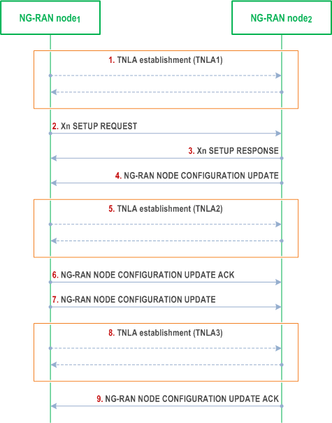
In the following, the procedure for managing multiple TNLAs for Xn-C is described.

Step 1.
The XnAP UE TNLA binding is a binding between a XnAP UE association and a specific TNL association for a given UE. After the XnAP UE TNLA binding is created, the NG-RAN node1 or the NG-RAN node2 can update the UE TNLA binding by sending the first available XnAP message for the UE to the peer NG-RAN node via a different TNLA. The peer NG-RAN node shall update the XnAP UE TNLA binding with the new TNLA.
The NG-RAN node1 establishes the first TNLA with the NG-RAN node2 using a configured TNL address.
Step 2-3.
Once the TNLA has been established, the NG-RAN node1 initiates the Xn Setup procedure to exchange application level configuration data.
Step 4-6.
The NG-RAN node2 may add additional TNL Endpoint(s) to be used for Xn-C signalling between the NG-RAN node1 and the NG-RAN node2 pair using the NG-RAN node Configuration Update procedure. NG-RAN node Configuration Update procedure also allows the NG-RAN node2 to request the NG-RAN node1 to modify or release TNLA(s).
Step 7-9.
The NG-RAN node1 may add additional TNL Endpoint(s) to be used for Xn-C signalling between the NG-RAN node1 and the NG-RAN node2 pair using the NG-RAN node Configuration Update procedure. NG-RAN node Configuration Update procedure also allows the NG-RAN node1 to request the NG-RAN node2 to modify or release TNLA(s).