Content for TS 38.401 Word version: 18.2.0
1…
5…
6…
6.1.4
6.1.5…
6.2…
7…
8…
8.2…
8.2.1.4…
8.2.2…
8.2.3…
8.2.4
8.2.5
8.3…
8.4…
8.4.4…
8.5…
8.9…
8.9.4…
8.9.6…
8.9.7…
8.10
8.11…
8.12…
8.13…
8.14…
8.15…
8.15.2…
8.16…
8.17…
8.17.3…
8.17.4
8.18…
8.19…
8.19.2
8.19.3
8.19.4…
8.21…
8.22…
8.23…
8.24…
9…
A…
8.19.2 Remote UE RRC Reestablishment p. 128
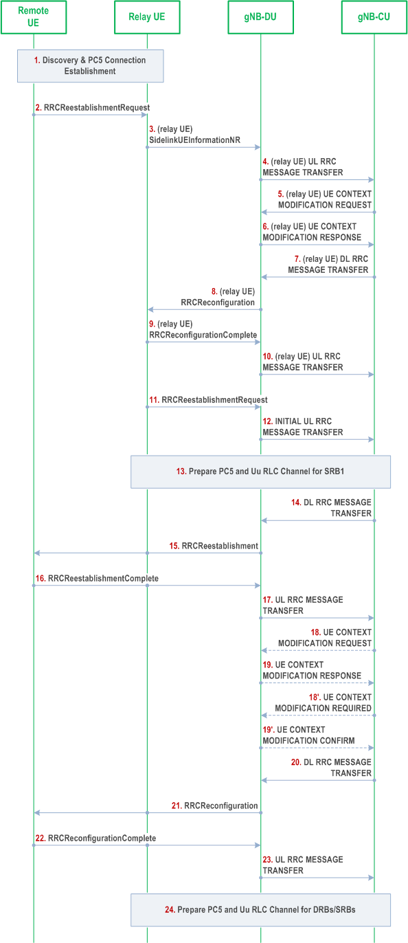
The signalling flow for Remote UE RRC Reestablishment is shown in Figure 8.19.2-1.

Step 1.
The U2N Remote UE and the U2N Relay UE perform discovery procedure, and establish PC5 connection using NR ProSe procedure. This step may be omitted if PC5 connection was established.
Step 2.
The U2N Remote UE sends an RRCReestablishmentRequest message to the U2N Relay UE via PC5 Relay RLC Channel.
Step 3~10.
The gNB-CU allocates the local ID of the U2N Remote UE if the U2N Relay UE does not have it. The details of those steps can be referred to clause 8.19.1.
Step 11.
After receiving the local ID of the U2N Remote UE, the U2N Relay UE sends the RRCReestablishmentRequest message of the U2N Remote UE to gNB-DU.
Step 12.
The gNB-DU allocates a C-RNTI and a gNB-DU UE F1AP ID for the U2N Remote UE and sends the INITIAL UL RRC MESSAGE TRANSFER message to gNB-CU by encapsulating the RRCReestablishmentRequest message of the U2N Remote UE. In addition, the local ID of the U2N Remote UE, the gNB-DU UE F1AP ID of the U2N Relay UE and the sidelink configuration container for at least the PC5 Relay RLC channel configuration for relaying of U2N Remote UE's SRB1 are included in the INITIAL UL RRC MESSAGE TRANSFER message.
Step 13.
The gNB-CU configures the U2N Relay UE with PC5 Relay RLC channel, Uu Relay RLC channel and bearer mapping for relaying of U2N Remote UE's SRB1. According to the configuration from gNB-CU, the U2N Relay UE establishes a PC5 Relay RLC channel for relaying of U2N Remote UE's SRB1 over PC5 and establishes a Uu Relay RLC channel for relaying of U2N Remote UE's SRB1 over Uu.
Step 14~23.
The details of those steps can be referred to Steps 5~14 in clause 8.7. For L2 U2N relay, the RRC message(s) between the U2N Remote UE and the gNB-DU are relayed via the U2N Relay UE; Steps 18~19 may additionally perform the configurations of PC5 Relay RLC channel(s) for relaying of U2N Remote UE's SRB1, SRB2 and DRBs.
Step 24.
The gNB-CU configures additional Uu Relay RLC channels between the gNB-DU and the U2N Relay UE, and additional PC5 Relay RLC channels for the U2N Relay UE for relaying of U2N Remote UE's DRBs and SRBs. Also, such step may configure the bearer mapping between U2N Remote UE's DRB/SRB and PC5/Uu Relay RLC channel at the U2N Relay UE.