Content for TS 38.401 Word version: 18.2.0
1…
5…
6…
6.1.4
6.1.5…
6.2…
7…
8…
8.2…
8.2.1.4…
8.2.2…
8.2.3…
8.2.4
8.2.5
8.3…
8.4…
8.4.4…
8.5…
8.9…
8.9.4…
8.9.6…
8.9.7…
8.10
8.11…
8.12…
8.13…
8.14…
8.15…
8.15.2…
8.16…
8.17…
8.17.3…
8.17.4
8.18…
8.19…
8.19.2
8.19.3
8.19.4…
8.21…
8.22…
8.23…
8.24…
9…
A…
8.19.4 Service Continuity for L2 U2N relay
8.19.4.1 Inter-gNB-DU switch from direct to indirect path
8.19.4.2 Intra-gNB-DU switch from direct to indirect path
8.19.4.3 Inter-gNB-CU switch from direct to indirect path
...
...
8.19.4 Service Continuity for L2 U2N relay p. 132
8.19.4.1 Inter-gNB-DU switch from direct to indirect path p. 132
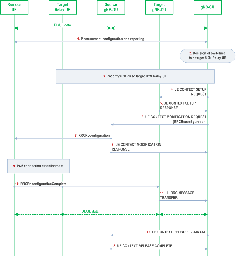
The signalling flow for U2N Remote UE switch from direct to indirect path with gNB-DU change is shown in Figure 8.19.4.1-1.

Step 1.
The Uu measurement configuration and measurement report signalling is performed between U2N Remote UE and gNB-CU to evaluate both relay link measurement and Uu link measurement. The U2N Remote UE may report one or multiple candidate U2N Relay UE(s) and Uu measurement results after it measures/discovers the candidate U2N Relay UE(s).
Step 2.
The gNB-CU decides to switch the U2N Remote UE to a target U2N Relay UE under a different gNB-DU (i.e., target gNB-DU).
Step 3.
The reconfiguration to target U2N Relay UE is performed among U2N Relay UE, the target gNB-DU and gNB-CU, if the U2N Relay UE is in RRC_CONNECTED state. The gNB-CU sends an RRCReconfiguration message to the target U2N Relay UE. If the target Relay UE is in RRC_IDLE/INACTIVE state, this step is skipped and the configuration to the target U2N Relay UE is performed in Step 10.
Step 4.
gNB-CU sends the UE CONTEXT SETUP REQUEST message for the U2N Remote UE to the target gNB-DU, which contains the path switch configuration at least.
Step 5.
gNB-DU responds with the UE CONTEXT SETUP RESPONSE message to gNB-CU.
Step 6.
gNB-CU sends the UE CONTEXT MODIFICATION REQUEST message by including the RRCReconfiguration message to the source gNB-DU. The contents in the RRCReconfiguration message may include at least path switch configuration, PC5 Relay RLC channel configuration for relaying traffic, bearer mapping configuration and the associated radio bearer(s).
Step 7.
The source gNB-DU sends the RRCReconfiguration message to the U2N Remote UE. The U2N Remote UE stops UP and CP transmission over Uu after reception of RRCReconfiguration message from the gNB.
Step 8.
The source gNB-DU sends the UE CONTEXT MODIFICATION RESPONSE message to the gNB-CU.
Step 9.
The U2N Remote UE establishes PC5 connection with target U2N Relay UE.
Step 10.
he U2N Remote UE completes the path switch procedure by sending the RRCReconfigurationComplete message to the target gNB-DU via the target U2N Relay UE. In case the U2N relay UE is in RRC_IDLE/ INACTIVE state, when the U2N relay UE receives the RRCReconfigurationComplete message, the reception of the RRCReconfigurationComplete message will first trigger RRC setup/resume procedure for the U2N relay UE to enter RRC_CONNECTED state.
Step 11.
The target gNB-DU sends the UL RRC MESSAGE TRANSFER message to gNB-CU by including the RRCReconfigurationComplete message.
Step 12.
The gNB-CU sends an UE CONTEXT RELEASE COMMAND message to the source gNB-DU.
Step 13.
The source gNB-DU releases the UE context and responds the gNB-CU with an UE CONTEXT RELEASE COMPLETE message.
8.19.4.2 Intra-gNB-DU switch from direct to indirect path p. 134
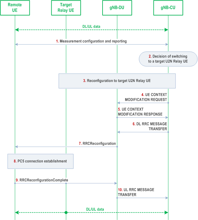
The signalling flow for U2N Remote UE switch from direct to indirect path without gNB-DU change is shown in Figure 8.19.4.2-1.

Step 1.
The Uu measurement configuration and measurement report signalling is performed between U2N Remote UE and gNB-CU to evaluate both relay link measurement and Uu link measurement. The U2N Remote UE may report one or multiple candidate U2N Relay UE(s) and Uu measurement results after it measures/discovers the candidate U2N Relay UE(s).
Step 2.
The gNB-CU decides to switch the U2N Remote UE to a target U2N Relay UE under the same gNB-DU.
Step 3.
The reconfiguration to target U2N Relay UE is performed among U2N Relay UE, gNB-DU and gNB-CU if U2N Relay UE is in RRC_CONNECTED state. The gNB-CU sends an RRCReconfiguration message to the target U2N Relay UE. If the target Relay UE is in RRC_IDLE/INACTIVE state, this step is skipped and the configuration to the target U2N Relay UE is performed in Step 9.
Step 4.
gNB-CU sends the UE CONTEXT MODIFICATION REQUEST message for the U2N Remote UE to gNB-DU, which contains the path switch configuration at least. The F1-U packets of the U2N Remote UE can be continuously transmitted via previous tunnels if there is no tunnel update in this step.
Step 5.
gNB-DU responds with the UE CONTEXT MODIFICATION RESPONSE message to gNB-CU.
Step 6.
gNB-CU sends the DL RRC MESSAGE TRANSFER message by including the RRCReconfiguration message to gNB-DU. The contents in the RRCReconfiguration message may include at least path switch configuration, PC5 Relay RLC channel configuration for relaying traffic, bearer mapping configuration and the associated radio bearer(s).
Step 7.
gNB-DU sends the RRCReconfiguration message to the U2N Remote UE. The U2N Remote UE stops UP and CP transmission over Uu after reception of RRCReconfiguration message from the gNB.
Step 8.
The U2N Remote UE establishes PC5 connection with target U2N Relay UE.
Step 9.
The U2N Remote UE completes the path switch procedure by sending the RRCReconfigurationComplete message to the gNB-DU via the target U2N Relay UE. In case the U2N Relay UE is in RRC_IDLE/INACTIVE state when receiving the RRCReconfigurationComplete message, the reception of the RRCReconfigurationComplete message will first trigger RRC setup/resume procedure for the U2N relay UE to enter RRC_CONNECTED state.
Step 10.
The gNB-DU sends the UL RRC MESSAGE TRANSFER message to gNB-CU by including the RRCReconfigurationComplete message.
8.19.4.3 Inter-gNB-CU switch from direct to indirect path |R18| p. 135
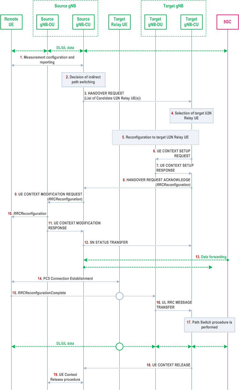
The inter-gNB-CU switch from direct to indirect path can be based on Xn handover procedure or NG handover procedure. The signalling flow for U2N Remote UE switch from direct to indirect path with gNB-CU change based on Xn handover procedure is shown in Figure 8.19.4.3-1.

Step 1.
The Uu measurement configuration and measurement report signalling are performed between U2N Remote UE and source gNB-CU to evaluate both relay link measurement and Uu link measurement. The U2N Remote UE may report one or multiple candidate U2N Relay UE(s) and Uu measurement results after it measures/discovers the candidate U2N Relay UE(s).
Step 2.
The source gNB-CU decides to switch the U2N Remote UE to one of the candidate U2N Relay UE(s).
Step 3.
The source gNB-CU sends the XnAP HANDOVER REQUEST message to the target gNB-CU. The HANDOVER REQUEST message include a list of candidate U2N Relay UE(s) IDs of same cell of the target gNB.
Step 4.
The target gNB-CU decides to accept the indirect path switching, and select the target U2N Relay UE from the candidate U2N Relay UE(s).
Step 5.
The reconfiguration to target U2N Relay UE is performed among target U2N Relay UE, the target gNB-DU and target gNB-CU, if the target U2N Relay UE is in RRC_CONNECTED state. The target gNB-CU allocates the local ID for the U2N Remote UE. The target gNB-CU sends an RRCReconfiguration message to the target U2N Relay UE. If the target U2N Relay UE is in RRC_IDLE/INACTIVE state, this step is skipped and the configuration to the target U2N Relay UE is performed in Step 15.
Step 6.
The target gNB-CU sends the UE CONTEXT SETUP REQUEST message for the U2N Remote UE to the target gNB-DU, which contains the path switch configuration at least.
Step 7.
The target gNB-DU responds with the UE CONTEXT SETUP RESPONSE message to the target gNB-CU.
Step 8.
The target gNB-CU responds the source gNB-CU with an XnAP HANDOVER REQUEST ACKNOWLEDGE message by including the RRCReconfiguration message. The contents in the RRCReconfiguration message may include at least path switch configuration, PC5 Relay RLC channel configuration for relay traffic, bearer mapping and the associated radio bearer(s).
Step 9.
The source gNB-CU sends to the source gNB-DU the UE CONTEXT MODIFICATION REQUEST message to send the handover command to the U2N Remote UE, and to indicate to stop the data transmission for the U2N Remote UE.
Step 10.
The source gNB-DU sends the RRCReconfiguration message to the U2N Remote UE. The U2N Remote UE stops UP and CP transmission over Uu after reception of RRCReconfiguration message from the source gNB.
Step 11.
The source gNB-DU sends the UE CONTEXT MODIFICATION RESPONSE message to the source gNB-CU.
Step 12.
The source gNB-CU sends an XnAP SN STATUS TRANSFER message to the target gNB-CU.
Step 13.
Data Forwarding may be performed from the source gNB-CU to the target gNB-CU.
Step 14.
The U2N Remote UE establishes PC5 connection with target U2N Relay UE.
Step 15.
The U2N Remote UE completes the path switch procedure by sending the RRCReconfigurationComplete message to the target gNB-DU via the target U2N Relay UE. In case the target U2N Relay UE is in RRC_IDLE/ INACTIVE state when receiving the RRCReconfigurationComplete message, the reception of the RRCReconfigurationComplete message will first trigger RRC setup/resume procedure for the target U2N Relay UE to enter RRC_CONNECTED state.
Step 16.
The target gNB-DU sends the UL RRC MESSAGE TRANSFER message to target gNB-CU by including the RRCReconfigurationComplete message.
Step 17.
Path Switch procedure is performed to switch the DL data path towards the target gNB-CU and to establish an NG-C interface instance towards the target gNB-CU.
Step 18.
The target gNB-CU sends an XnAP UE CONTEXT RELEASE message to the source gNB-CU.
Step 19.
The source gNB-CU sends an UE CONTEXT RELEASE COMMAND message to the source gNB-DU to release the UE context of the U2N Remote UE in the source gNB-DU.
Step 20.
The source gNB-DU releases the UE context of the U2N Remote UE, and responds the gNB-CU with an UE CONTEXT RELEASE COMPLETE message.