Content for TS 38.401 Word version: 18.2.0
1…
5…
6…
6.1.4
6.1.5…
6.2…
7…
8…
8.2…
8.2.1.4…
8.2.2…
8.2.3…
8.2.4
8.2.5
8.3…
8.4…
8.4.4…
8.5…
8.9…
8.9.4…
8.9.6…
8.9.7…
8.10
8.11…
8.12…
8.13…
8.14…
8.15…
8.15.2…
8.16…
8.17…
8.17.3…
8.17.4
8.18…
8.19…
8.19.2
8.19.3
8.19.4…
8.21…
8.22…
8.23…
8.24…
9…
A…
8.2.4 Intra-CU topological redundancy procedure |R16| p. 51
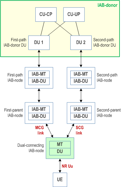
The intra-CU topological redundancy procedure enables the establishment and release of redundant paths in the IAB-topology underneath the same IAB-donor-CU. The redundant paths may use different IAB-donor-DUs. They may also have common intermediate nodes. Since topological redundancy uses NR-DC for the IAB-MT, it is only supported for IAB-nodes operating in SA mode. Figure 8.2.4-1 shows an example for an IAB topology, where one IAB-node, referred to as the dual-connecting IAB-node, has two paths towards the IAB-donor via different IAB-donor-DUs.


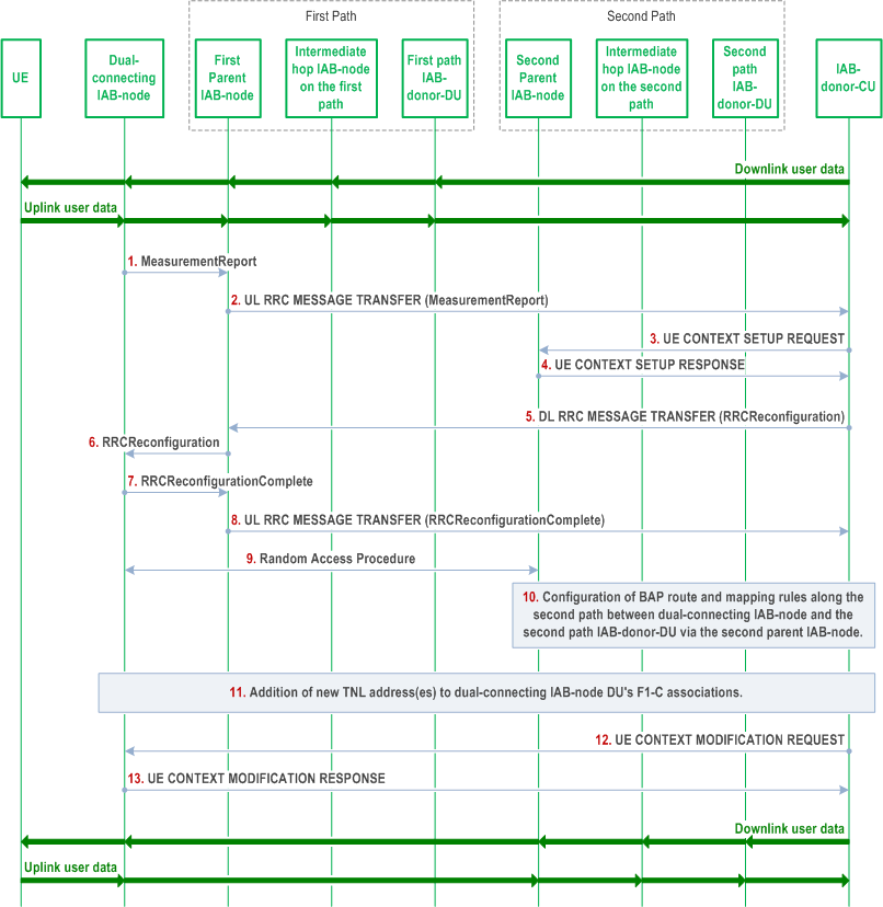
Figure 8.2.4-2 shows the procedure for the establishment of the second path. This procedure has the following steps:
Step 1.
Steps 12 and 13 can be performed for a subset of UE bearers, e.g., to balance the load between the first and the second path.
In case the second path is used for the dual-connecting IAB-node's descendant node(s), Steps 10 and 11 are also performed for the descendant node(s), as follows:
The dual-connecting IAB-MT sends a MeasurementReport message to the first parent node IAB-DU. This report is based on a Measurement Configuration the dual-connecting IAB-MT received from the IAB-donor-CU before.
Step 2.
The first parent node IAB-DU sends an UL RRC MESSAGE TRANSFER message to the IAB-donor-CU to convey the received MeasurementReport.
Step 3.
The IAB-donor-CU sends the UE CONTEXT SETUP REQUEST message to the second parent node IAB-DU, to create the UE context for the dual-connecting IAB-MT and to set up one or more bearers. These bearers can be used by the dual-connecting IAB-MT for its own signalling, and, optionally, data traffic.
Step 4.
The second parent node IAB-DU responds to the IAB-donor-CU with a UE CONTEXT SETUP RESPONSE message.
Step 5.
The IAB-donor-CU sends a DL RRC MESSAGE TRANSFER message to the first parent node IAB-DU, which includes a generated RRCReconfiguration message. The RRCReconfiguration message may contain one or more TNL address(es) for the dual-connecting IAB-DU, which are anchored at the second-path IAB-donor-DU. The IAB-donor-CU can proactively obtain these TNL addresses from the second-path IAB-donor-DU. In case IPsec tunnel mode is used to protect the F1 and non-F1 traffic, the allocated TNL address is the outer IP address. The TNL address allocation is not necessary if the first and second paths use the same IAB-donor-DU.
Step 6.
The first parent node IAB-DU forwards the received RRCReconfiguration message to the dual-connecting IAB-MT.
Step 7.
The dual-connecting IAB-MT responds to the first parent node IAB-DU with an RRCReconfigurationComplete message.
Step 8.
The first parent node IAB-DU sends an UL RRC MESSAGE TRANSFER message to the IAB-donor-CU, to convey the received RRCReconfigurationComplete message.
Step 9.
A Random Access procedure is performed at the second parent node IAB-DU.
Step 10.
The IAB-donor-CU configures BH RLC channels and BAP-layer route entries on the second path between dual-connecting IAB-node and second-path IAB-donor-DU. These configurations may be performed at an earlier stage, e.g. immediately after step 3.
Step 11.
The new TNL addresses allocated in step 5 (if any) are added to the dual-connecting IAB-DU's F1-C association(s) with the IAB-donor-CU. The IAB-donor-CU may configure new UL BH information on the second path for F1AP messages.
If new TNL addresses for F1-C traffic are configured, new SCTP association(s) between the dual-connecting IAB-node and the IAB-donor-CU may be established using the new TNL address information of the dual-connecting IAB-node. The dual-connecting IAB-node sends an F1AP gNB-DU CONFIGURATION UPDATE message to the IAB-donor-CU, which may include new (outer) IP addresses and corresponding new (inner) IP address for the F1-U traffic to be switched to the target path.
Step 12.
The IAB-donor-CU may migrate the F1-U tunnels it has with the dual-connecting IAB-DU from the first path to the second path via the UE CONTEXT MODIFICATION REQUEST message.
Step 13.
The dual-connectivity IAB-DU replies with a UE CONTEXT MODIFICATION RESPONSE message.
When the second path uses a different IAB-donor-DU, the IAB-donor-CU shall configure the descendent IAB-DU(s) with one or more new TNL addresses, which are anchored on the IAB-donor-DU of the second path.
If needed, the IAB-donor-CU configures BH RLC channels, BAP-layer route entries on the target path for the descendant nodes and the BH RLC channel mappings on the descendant nodes in the same manner as described for the dual-connecting IAB-node in step 10.
The descendant nodes' new TNL addresses (if any) are added to the descendant node IAB-DU's F1-C association(s) with the IAB-donor-CU. The IAB-donor-CU may configure UL BH information for the second path to carry F1AP messages.
The IAB-donor-CU may migrate the F1-U tunnels it has with the dual-connecting IAB-node's descendant node(s) from the first path to the second path, as described for step 12.
Based on implementation, these steps can be performed after or in parallel with the redundant path addition of the dual connecting IAB-node.
The IAB-donor-CU may initiate the release of the redundant path by releasing the BAP routing entries and modifying/releasing the BH RLC channels on that path.