Content for TS 38.401 Word version: 18.2.0
1…
5…
6…
6.1.4
6.1.5…
6.2…
7…
8…
8.2…
8.2.1.4…
8.2.2…
8.2.3…
8.2.4
8.2.5
8.3…
8.4…
8.4.4…
8.5…
8.9…
8.9.4…
8.9.6…
8.9.7…
8.10
8.11…
8.12…
8.13…
8.14…
8.15…
8.15.2…
8.16…
8.17…
8.17.3…
8.17.4
8.18…
8.19…
8.19.2
8.19.3
8.19.4…
8.21…
8.22…
8.23…
8.24…
9…
A…
8.5 F1 Startup and cells activation
8.6 RRC state transition
8.6.1 RRC connected to RRC inactive
8.6.2 RRC inactive to other states
8.7 RRC connection reestablishment
8.8 Multiple TNLAs for F1-C
...
...
8.5 F1 Startup and cells activation p. 61
This function allows to setup the F1 interface between a gNB-DU and a gNB-CU and it allows to activate the gNB-DU cells.
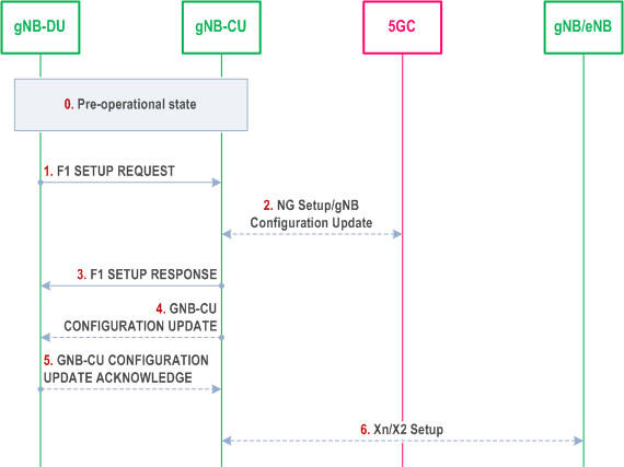
Step 0.
Over the F1 interface between a gNB-CU and a gNB-DU pair, the following two Cell States are possible:
The gNB-DU and its cells are configured by OAM in the F1 pre-operational state. The gNB-DU has TNL connectivity toward the gNB-CU.
Step 1.
The gNB-DU sends an F1 SETUP REQUEST message to the gNB-CU including a list of cells that are configured and ready to be activated. For each cell supporting NPN the gNB-DU includes NPN specific information.
Step 2.
In NG-RAN, the gNB-CU ensures the connectivity toward the core network. For this reason, the gNB-CU may initiate either the NG Setup or the gNB Configuration Update procedure towards 5GC.
Step 3.
The gNB-CU sends an F1 SETUP RESPONSE message to the gNB-DU that optionally includes a list of cells to be activated. The cells in the list of cells to be activated in F1 SETUP RESPONSE message become active, while the cells not in the list are inactive. The cells that are active are Out-of-Service until the gNB-DU indicates that they are In-Service. The gNB-DU will initiate the gNB-DU Configuration Update procedure towards the gNB-CU and includes the cell(s) that are In-Service and/or the cell(s) that are Out-Of-Service. The gNB-DU may also indicate cell(s) to be deleted, in which case the gNB-CU removes the corresponding cell(s) information.
Step 4.
The gNB-CU may send a GNB CU CONFIGURATION UPDATE message to the gNB-DU that optionally includes a list of cells to be activated, e.g., in case that these cells were not activated using the F1 SETUP RESPONSE message.
Step 5.
The gNB-DU replies with a GNB CU CONFIGURATION UPDATE ACKNOWLEDGE message that optionally includes a list of cells that failed to be activated. The gNB-CU regards all Active cells as Out-Of-Service until the gNB-DU indicates that they are In-Service.
Step 6.
The gNB-CU may initiate either the Xn Setup towards a neighbour NG-RAN node or the EN-DC X2 Setup procedure towards a neighbour eNB.
- Inactive: the cell is known by both the gNB-DU and the gNB-CU. The cell shall not serve UEs;
- Active: the cell is known by both the gNB-DU and the gNB-CU. The cell should try to provide services to the UEs.
- In-Service: the cell is operational and able to serve UEs.
- Out-Of-Service: the cell is not operational, and it is not able to serve UEs. The gNB-DU is trying to make the cell operational.
8.6 RRC state transition p. 63
8.6.1 RRC connected to RRC inactive p. 63
This clause gives the RRC connected to RRC inactive state transition given that gNB consists of gNB-CU and gNB-DU(s), as shown in Figure 8.6.1-1.
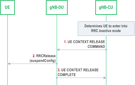
Step 0.
At first, the gNB-CU determines the UE to enter into RRC inactive mode from connected mode.
Step 1.
The gNB-CU generates RRCRelease message which includes suspend configuration towards UE. The RRC message is encapsulated in UE CONTEXT RELEASE COMMAND message to the gNB-DU.
Step 2.
The gNB-DU forwards RRCRelease message to UE.
Step 3.
The gNB-DU responds with UE CONTEXT RELEASE COMPLETE message.
8.6.2 RRC inactive to other states p. 63
This clause gives the RRC inactive to other RRC states transition given that gNB consists of gNB-CU and gNB-DU(s), as shown in Figure 8.6.2-1.
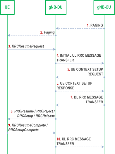
Step 1.
If data is received from 5GC, the gNB-CU sends PAGING message to the gNB-DU.
Step 2.
The gNB-DU sends Paging message to UE.
Step 3.
The UE sends RRCResumeRequest message either upon RAN-based paging, UL data arrival or RNA update.
Step 4.
The gNB-DU includes RRCResumeRequest in a non-UE associated INITIAL UL RRC MESSAGE TRANSFER message and transfer to the gNB-CU.
Step 5.
For UE Inactive to UE Active transitions, excluding transitions due to signalling exchange only, the gNB-CU allocates gNB-CU UE F1AP ID and sends UE CONTEXT SETUP REQUEST message to gNB-DU, which may include SRB ID(s) and DRB ID(s) to be setup, CellGroupConfig stored in gNB-CU or retrieved from the old NG-RAN node may also be included. In case of NG-RAN sharing, the gNB-CU includes the serving PLMN ID (in case of SNPNs the serving NID).
Step 6.
The gNB-DU responds with UE CONTEXT SETUP RESPONSE message, which contains RLC/MAC/PHY configuration of SRB and DRBs provided by the gNB-DU.
Step 7.
The gNB-CU generates RRCResume/RRCSetup/RRCReject/RRCRelease message or receives RRCRelease message from the old NG-RAN node towards the UE. The RRC message is encapsulated in DL RRC MESSAGE TRANSFER message together with SRB ID.
Step 8.
The gNB-DU forwards RRC message to the UE either over SRB0 or SRB1 as indicated by the SRB ID.
If step 5 and 6 are not performed, the gNB-DU deduces the SRB on which to deliver the RRC message in step 7 from the SRB ID, i.e. SRB ID "0" corresponds to SRB0, SRB ID "1" corresponds to SRB1.
Step 9.
The UE sends RRCResumeComplete/RRCSetupComplete message to the gNB-DU.
Step 10.
The gNB-DU encapsulates RRC in UL RRC MESSAGE TRANSFER message and send to the gNB-CU.
8.7 RRC connection reestablishment p. 65
This procedure is used for the case that UE tries to reestablish the RRC connection, as shown in Figure 8.7-1.
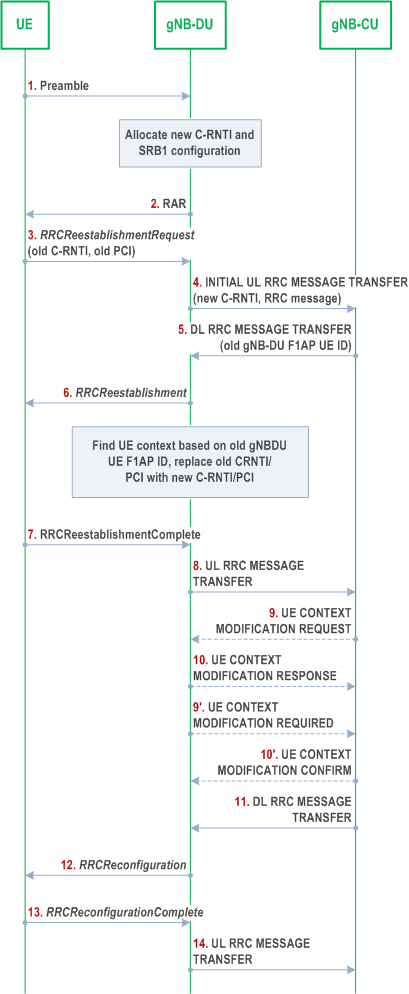
Step 1.
The UE sends a preamble to the gNB-DU.
Step 2.
The gNB-DU allocates new C-RNTI and responds with RAR.
Step 3.
The UE sends an RRCReestablishmentRequest message to the gNB-DU, which contains old C-RNTI and old PCI.
Step 4.
The gNB-DU includes the RRC message and, if the UE is admitted, the corresponding low layer configuration for the UE in the INITIAL UL RRC MESSAGE TRANSFER message and transfers to the gNB-CU. The INITIAL UL RRC MESSAGE TRANSFER message includes the new C-RNTI. If the gNB-DU identifies the UE as a Reduced Capability UE during the random access procedure, a NR RedCap UE Indication is provided in the INITIAL UL RRC MESSAGE TRANSFER message.
Step 5.
The gNB-CU includes an RRCReestablishment message and transfers to the gNB-DU. If the UE requests to re-establish RRC connection in the last serving gNB-DU, the DL RRC MESSAGE TRANSFER message shall include old gNB-DU UE F1AP ID.
Step 6.
The gNB-DU retrieves the UE context based on the old gNB-DU UE F1AP ID, and replaces old C-RNTI/PCI with new C-RNTI/PCI. It sends the RRCReestablishment message to UE.
Step 7-8.
The UE sends an RRCReestablishmentComplete message to the gNB-DU. The gNB-DU encapsulates the RRC message in the UL RRC MESSAGE TRANSFER message and sends to the gNB-CU.
Step 9-10.
The gNB-CU triggers an UE Context Modification procedure by sending UE CONTEXT MODIFICATION REQUEST message, which may include DRBs to be modified and released list. The gNB-DU responses with the UE CONTEXT MODIFICATION RESPONSE message.
Step 9'-10'.
The gNB-DU triggers an UE Context Modification procedure by sending UE CONTEXT MODIFICATION REQUIRED message, which may include DRBs to be modified and released list. The gNB-CU responses with UE CONTEXT MODIFICATION CONFIRM message.
Step 11-12.
The gNB-CU includes an RRCReconfiguration message into the DL RRC MESSAGE TRANSFER message and transfers to the gNB-DU. The gNB-DU forwards it to the UE.
Step 13-14.
The UE sends an RRCReconfigurationComplete message to the gNB-DU, and the gNB-DU forwards it to the gNB-CU.
8.8 Multiple TNLAs for F1-C p. 67
In the following, the procedure for managing multiple TNLAs for F1-C is described.
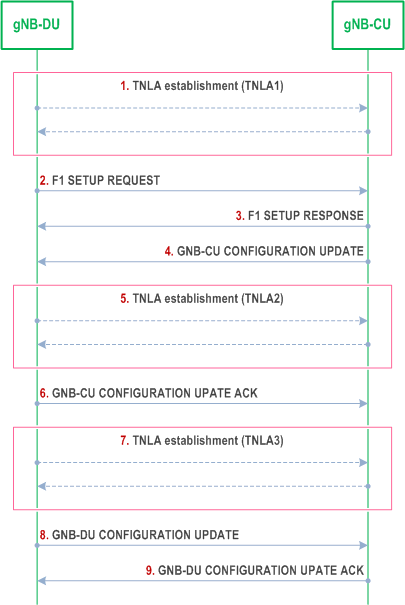
Step 1.
The F1AP UE TNLA binding is a binding between a F1AP UE association and a specific TNL association for a given UE. After the F1AP UE TNLA binding is created, the gNB-CU can update the UE TNLA binding by sending the F1AP message for the UE to the gNB-DU via a different TNLA. The gNB-DU shall update the F1AP UE TNLA binding with the new TNLA. The gNB-DU Configuration Update procedure also allows the gNB-DU to inform the gNB-CU that the indicated TNLA(s) will be removed by the gNB-DU.
The gNB-DU establishes the first TNLA with the gNB-CU using a configured TNL address.
Step 2-3.
Once the TNLA has been established, the gNB-DU initiates the F1 Setup procedure to exchange application level configuration data.
Step 4-6.
The gNB-CU may add additional TNL Endpoint(s) to be used for F1-C signalling between the gNB-CU and the gNB-DU pair using the gNB-CU Configuration Update procedure. The gNB-CU Configuration Update procedure also allows the gNB-CU to request the gNB-DU to modify or release TNLA(s).
Step 7-9.
The gNB-DU may add additional TNL association(s) to be used for F1-C signalling using a gNB-CU endpoint already in use for existing TNL associations between the gNB-CU and the gNB-DU pair. The gNB-DU CONFIGURATION UPDATE message including the gNB-DU ID shall be the first F1AP message sent on an additional TNLA of an already setup F1-C interface instance after the TNL association has become operational.