Content for TS 38.401 Word version: 18.2.0
1…
5…
6…
6.1.4
6.1.5…
6.2…
7…
8…
8.2…
8.2.1.4…
8.2.2…
8.2.3…
8.2.4
8.2.5
8.3…
8.4…
8.4.4…
8.5…
8.9…
8.9.4…
8.9.6…
8.9.7…
8.10
8.11…
8.12…
8.13…
8.14…
8.15…
8.15.2…
8.16…
8.17…
8.17.3…
8.17.4
8.18…
8.19…
8.19.2
8.19.3
8.19.4…
8.21…
8.22…
8.23…
8.24…
9…
A…
8.19 Overall procedures for L2 UE-to-Network Relay |R17| p. 125
8.19.1 Remote UE initial access p. 125
The signalling flow for Remote UE Initial access is shown in Figure 8.19.1-1.
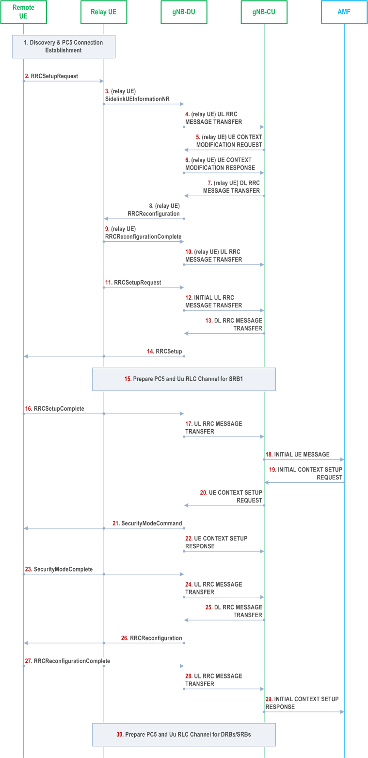
Step 1.
The U2N Remote UE and the U2N Relay UE perform discovery procedure, and establish PC5 connection using NR ProSe procedure.
Step 2.
The U2N Remote UE sends an RRCSetupRequest message to the U2N Relay UE via PC5 Relay RLC Channel.
Step 3.
The U2N Relay UE withholds the received RRC message and sends the SidelinkUEInformationNR message to the gNB-DU. Before that, if the U2N Relay UE is in RRC_IDLE/RRC_INACTIVE state, it should trigger the RRC establishment/resume procedure to enter RRC_CONNECTED state and gNB may configure the U2N Relay UE with Uu Relay RLC channel(s) for relaying of U2N Remote UE's SRB0/1.
Step 4.
The gNB-DU sends the UL RRC MESSAGE TRANSFER message of the U2N Relay UE by encapsulating the SidelinkUEInformationNR message to gNB-CU, and gNB-CU allocates the local ID of U2N Remote UE.
Step 5.
The gNB-CU sends the UE CONTEXT MODIFICATION REQUEST message of the U2N Relay UE to gNB-DU. Such message may request the establishment of Uu Relay RLC channel(s) for the transmission of U2N Remote UE's SRB0/1 if not configured yet.
Step 6.
The gNB-DU sends the UE CONTEXT MODIFICATION RESPONSE message of the U2N Relay UE to gNB-CU.
Step 7.
The gNB-CU sends the DL RRC MESSAGE TRANSFER message of the U2N Relay UE to gNB-DU by encapsulating the RRCReconfiguration message, which contains the local ID allocated to the U2N Remote UE. The RRCReconfiguration message shall also contain the Uu Relay RLC channel(s) configuration if not configured and bearer mapping for relaying of U2N Remote UE's SRB0/1.
Step 8.
The gNB-DU sends the RRCReconfiguration message to the U2N Relay UE to configure the local ID of the U2N Remote UE, the Uu Relay RLC channel(s) configuration and bearer mapping for relaying of U2N Remote UE's SRB0/1.
Step 9.
The U2N Relay UE sends the RRCReconfigurationComplete message to gNB-DU.
Step 10.
The gNB-DU sends the UL RRC MESSAGE TRANSFER message of the U2N Relay UE by encapsulating the RRCReconfigurationComplete message to gNB-CU.
Step 11.
After receiving the local ID of the U2N Remote UE and the Uu Relay RLC channel(s) configuration and bearer mapping for relaying of U2N Remote UE's SRB0, the U2N Relay UE sends the RRCSetupRequest message of the U2N Remote UE to gNB-DU. The local ID of the U2N Remote UE and RB ID for SRB0 are conveyed in the SRAP header.
Step 12.
The gNB-DU allocates a C-RNTI and a gNB-DU UE F1AP ID for the U2N Remote UE and sends the INITIAL UL RRC MESSAGE TRANSFER message to gNB-CU by encapsulating the RRCSetupRequest message of the U2N Remote UE. In addition, the local ID of the U2N Remote UE , the gNB-DU UE F1AP ID of the U2N Relay UE and the sidelink configuration container for at least the PC5 Relay RLC channel configuration for relaying of U2N Remote UE's SRB1 are included in the INITIAL UL RRC MESSAGE TRANSFER message.
Step 13.
The gNB-CU allocates a gNB-CU UE F1AP ID for the U2N Remote UE and generates a RRCSetup message towards the U2N Remote UE. The RRC message is encapsulated in the DL RRC MESSAGE TRANSFER message, and includes the configurations of PC5 Relay RLC channel and bearer mapping at least for the transmission of U2N Remote UE's SRB1.
Step 14.
The gNB-DU sends the RRCSetup message to the U2N Remote UE via the U2N Relay UE.
Step 15.
The gNB-CU configures the U2N Relay UE with PC5 Relay RLC channel, Uu Relay RLC channel and bearer mapping for relaying of U2N Remote UE's SRB1. According to the configuration from gNB-CU, the U2N Relay UE establishes a PC5 Relay RLC channel for relaying of U2N Remote UE's SRB1 over PC5 and establishes a Uu Relay RLC channel for relaying of U2N Remote UE's SRB1 towards gNB-DU if not configured yet.
Step 16.
The U2N Remote UE sends the RRCSetupComplete message to the gNB-DU via the U2N Relay UE.
Step 17.
The gNB-DU encapsulates the RRC message in the UL RRC MESSAGE TRANSFER message and sends it to the gNB-CU.
Step 18.
Upon receiving the RRCSetupComplete message of U2N Remote UE, the gNB-CU sends the INITIAL UE MESSAGE message to the AMF.
Step 19.
The AMF sends the INITIAL CONTEXT SETUP REQUEST message to the gNB-CU.
Step 20.
The gNB-CU sends the UE CONTEXT SETUP REQUEST message to establish the U2N Remote UE context in the gNB-DU. Such message may request the configuration of PC5 Relay RLC channels for the transmission of U2N Remote UE's SRB2 and DRBs, and may also encapsulate the SecurityModeCommand message.
Step 21.
The gNB-DU sends the SecurityModeCommand message to the U2N Remote UE via U2N Relay UE.
Step 22.
The gNB-DU sends the UE CONTEXT SETUP RESPONSE message of the U2N Remote UE to the gNB-CU, which contains the configuration of PC5 Relay RLC channels for the transmission of U2N Remote UE's SRB2 and DRBs.
Step 23.
The U2N Remote UE responds with the SecurityModeComplete message.
Step 24.
The gNB-DU encapsulates the RRC message in the UL RRC MESSAGE TRANSFER message and sends it to the gNB-CU.
Step 25.
The gNB-CU generates the RRCReconfiguration message for U2N Remote UE and encapsulates it in the DL RRC MESSAGE TRANSFER message. The RRCReconfiguration message contains the configuration of PC5 Relay RLC channels and bearer mapping for the transmission of U2N Remote UE's SRB2 and DRBs.
Step 26.
The gNB-DU sends RRCReconfiguration message to the U2N Remote UE via the U2N Relay UE.
Step 27.
The U2N Remote UE sends RRCReconfigurationComplete message to the gNB-DU via the U2N Relay UE.
Step 28.
The gNB-DU encapsulates the RRC message in the UL RRC MESSAGE TRANSFER message and send it to the gNB-CU.
Step 29.
The gNB-CU sends the INITIAL CONTEXT SETUP RESPONSE message to the AMF.
Step 30.
The gNB-CU configures additional Uu Relay RLC channels between the gNB-DU and the U2N Relay UE, and additional PC5 Relay RLC channels for the U2N Relay UE for relaying of U2N Remote UE's DRBs and SRBs. Also, such step may configure the bearer mapping between U2N Remote UE's DRB/SRB and PC5/Uu Relay RLC channel at the U2N Relay UE.
![]()
![]()
![]()