TS 37.480
E1 Interface
General Aspects and Principles
V18.1.0 (PDF)
2024/03 15 p.
V17.2.0
2023/12 15 p.
Content for TS 37.480 Word version: 17.1.0
1 Scope p. 5
The present document is an introduction to the 3GPP TS 37.48x series of technical specifications that define the E1 interface. The E1 interface provides means for interconnecting a gNB-CU-CP and a gNB-CU-UP of a gNB-CU within an NG-RAN, or for interconnecting a gNB-CU-CP and a gNB-CU-UP of an en-gNB within an E-UTRAN, or for interconnecting an eNB-CP and an eNB-UP of an eNB within an E-UTRAN, or for interconnecting an ng-eNB-CU-CP and an ng-eNB-CU-UP of an ng-eNB-CU within an NG-RAN.
2 References p. 5
The following documents contain provisions which, through reference in this text, constitute provisions of the present document.
- References are either specific (identified by date of publication, edition number, version number, etc.) or non-specific.
- For a specific reference, subsequent revisions do not apply.
- For a non-specific reference, the latest version applies. In the case of a reference to a 3GPP document (including a GSM document), a non-specific reference implicitly refers to the latest version of that document in the same Release as the present document.
[1]
TR 21.905: "Vocabulary for 3GPP Specifications".
[2]
TS 38.401: "NG-RAN; Architecture Description".
[3]
TS 37.481: "E1 layer 1".
[4]
TS 37.482: "E1 signalling transport".
[5]
TS 37.483: "E1 Application Protocol (E1AP)".
[6]
TS 38.300: "NR; Overall description; Stage-2".
[7]
TS 37.340: "NR; Multi-connectivity; Overall description; Stage-2".
[8]
TS 37.470: "W1 interface; General aspects and principles".
[9]
TS 36.401: "Evolved Universal Terrestrial Radio Access Network (E-UTRAN); Architecture description".
[10]
TS 23.247: "5G multicast-broadcast services; Stage 2".
3 Definitions and abbreviations p. 5
3.1 Definitions p. 5
For the purposes of the present document, the terms and definitions given in TR 21.905 and the following apply. A term defined in the present document takes precedence over the definition of the same term, if any, in TR 21.905.
eNB-CP:
as defined in TS 36.401.
eNB-UP:
as defined in TS 36.401.
en-gNB:
as defined in TS 37.340.
gNB-CU:
as defined in TS 38.401.
gNB-CU-CP:
as defined in TS 38.401.
gNB-CU-UP:
as defined in TS 38.401.
gNB-DU:
as defined in TS 38.401.
gNB:
as defined in TS 38.300.
IAB:
as defined in TS 38.300.
ng-eNB-CU:
as defined in TS 37.470.
ng-eNB-CU-CP:
as defined in TS 38.401.
ng-eNB-CU-UP:
as defined in TS 38.401.
ng-eNB-DU:
as defined in TS 37.470.
3.2 Abbreviations p. 5
For the purposes of the present document, the abbreviations given in TR 21.905 and the following apply. An abbreviation defined in the present document takes precedence over the definition of the same abbreviation, if any, in TR 21.905.
DL
Downlink
DRB
Data Radio Bearer
E1AP
E1 Application Protocol
IP
Internet Protocol
MBS
Multicast/Broadcast Service
PTP
Point to Point
PTM
Point to Multipoint
SCTP
Stream Control Transmission Protocol
TNL
Transport Network Layer
4 General aspects p. 6
This clause captures the E1 interface principles and characteristics.
4.1 E1 interface general principles p. 6
The general principles for the specification of the E1 interface are as follows:
- the E1 interface is open;
- the E1 interface supports the exchange of signalling information between the endpoints;
- from a logical standpoint, the E1 is a point-to-point interface between a gNB-CU-CP and a gNB-CU-UP, or between an ng-eNB-CU-CP and an ng-eNB-CU-UP, or between an eNB-CP and an eNB-UP.
- the E1 interface separates Radio Network Layer and Transport Network Layer;
- the E1 interface enables exchange of UE associated information and non-UE associated information;
- the E1 interface is future proof to fulfil different new requirements, support of new services and new functions.
4.2 E1 interface specification objectives p. 7
The E1 interface specifications facilitate the following:
- inter-connection of a gNB-CU-CP and a gNB-CU-UP supplied by different manufacturers.
- inter-connection of an ng-eNB-CU-CP and an ng-eNB-CU-UP supplied by different manufacturers.
- inter-connection of an eNB-CP and an eNB-UP supplied by different manufacturers.
5 Functions of the E1 interface p. 7
5.1 General p. 7
The following clauses describe the functions supported over E1.
5.1.1 E1 interface management function p. 7
The error indication function is used by the gNB-CU-UP or gNB-CU-CP to indicate to the gNB-CU-CP or gNB-CU-UP that an error has occurred.
The reset function is used to initialize the peer entity after node setup and after a failure event occurred. This procedure can be used by both the gNB-CU-UP and the gNB-CU-CP.
The E1 setup function allows to exchange application level data needed for the gNB-CU-UP and gNB-CU-CP to interoperate correctly on the E1 interface. The E1 setup is initiated by both the gNB-CU-UP and gNB-CU-CP.
The gNB-CU-UP Configuration Update and gNB-CU-CP Configuration Update functions allow to update application level configuration data needed between the gNB-CU-CP and the gNB-CU-UP to interoperate correctly over the E1 interface.
The E1 setup and gNB-CU-UP Configuration Update functions allow to inform NR CGI(s), ECGI(s), S-NSSAI(s), PLMN-ID(s), QoS information and NID(s) supported by the gNB-CU-UP.
The E1 setup and gNB-CU-UP Configuration Update functions allow the gNB-CU-UP to signal its capacity information to the gNB-CU-CP.
The E1 gNB-CU-UP Status Indication function allows to inform the overloaded or non-overloaded status over the E1 interface.
5.1.2 E1 bearer context management function p. 7
The establishment of the E1 bearer context is initiated by the gNB-CU-CP and accepted or rejected by the gNB-CU-UP based on admission control criteria (e.g., resource not available).
The modification of the E1 bearer context can be initiated by either gNB-CU-CP or gNB-CU-UP. The receiving node can accept or indicate failure to carry out the modification request. The E1 bearer context management function also supports the release of the bearer context previously established in the gNB-CU-UP. The release of the bearer context is triggered by the gNB-CU-CP either directly or following a request received from the gNB-CU-UP.
This function is used to setup and modify the QoS-flow to DRB mapping configuration. The gNB-CU-CP decides flow-to-DRB mapping and provides the generated SDAP and PDCP configuration to the gNB-CU-UP. The gNB-CU-CP also decides the Reflective QoS flow to DRB mapping. The function is also used to send to the gNB-CU-UP the alternative QoS Parameters Sets when available for a QoS flow. For each PDU Session Resource to be setup or modified, the S-NSSAI, shall be provided in the E1 bearer context setup procedure and may be provided in the E1 bearer context modification procedure by gNB-CU-CP to the gNB-CU-UP.
This function is also used to setup and modify the EPS bearer/E-RAB to DRB mapping configuration for the case of eNB-CP and eNB-UP separation. The eNB-CP decides EPS bearer/E-RAB-to-DRB mapping and provides the E-UTRAN/NR PDCP configuration to the eNB-UP.
This function is used for the gNB-CU-CP to send the security information to the gNB-CU-UP.
This function is used for the gNB-CU-CP to send to the gNB-CU-UP transport layer information to be used for data forwarding e.g., during handovers.
This function is used for the gNB-CU-CP to send the parameters for header compression for certain traffic types e.g., IP, Ethernet to the gNB-CU-UP.
This function is used for the gNB-CU-CP to send the uplink data compression parameters to the gNB-CU-UP for certain data radio bearer(s).
This function is used for the gNB-CU-UP to notify the event of DL data arrival detection to the gNB-CU-CP. With this function, the gNB-CU-UP requests gNB-CU-CP to trigger paging procedure over F1 or Xn to support RRC Inactive state. RRC Inactive state is not supported when this function is used between an eNB-CP and an eNB-UP.
This function is used for the gNB-CU-UP to notify the gNB-CU-CP that a DL packet including a QFI value not configured by the gNB-CU-CP or an UL packet including a QFI value in the SDAP header of the default DRB not configured by the gNB-CU-CP is received for the first time. The gNB-CU-CP can take further action if needed.
This function is used for the gNB-CU-UP to notify the event of user inactivity to the gNB-CU-CP. With this function, the gNB-CU-UP indicates that the inactivity timer associated with a bearer, a PDU session or a UE expires, or that user data is received for the bearer, the PDU session or the UE whose inactivity timer has expired. The gNB-CU-CP consolidates all the serving gNB-CU-UPs for the UE and takes further action.
This function is used for the gNB-CU-UP to report data volume to the gNB-CU-CP.
This function is used for the gNB-CU-CP to notify the suspension and resumption of bearer contexts to the gNB-CU-UP. Suspension and resumption of bearer contexts are not applicable to eNB-CP/eNB-UP and ng-eNB-CU-CP/ng-eNB-CU-UP.
This function also allows to support CA based packet duplication as described in TS 38.300, i.e. one data radio bearer should be configured with at least two GTP-U tunnels between gNB-CU-UP and a gNB-DU.
This function is used to support the enhanced mobility operations as described in TS 38.300 in the gNB-CU-UP.
5.1.3 Trace function p. 8
The Trace function provides means to control trace sessions for a UE over E1 interface.
5.1.4 Load management function p. 8
The load management function allows an gNB-CU-CP to request the reporting of load measurements to gNB-DU and is used by gNB-CU-UP to report the result of measurements admitted by gNB-CU-UP.
5.1.5 Measurement results transfer function p. 8
The measurement results transfer is used by the gNB-CU-CP to transfer UE associated measurement results to the gNB-CU-UP.
5.1.6 Support for IAB p. 8
This function is used to update the DL/UL F1-U GTP-U tunnels for an IAB network, and allow the gNB-CU-CP to send the security key info to the gNB-CU-UP for the protection of the F1-U interface with IAB-DU.
5.1.7 E1 bearer context management function for NR MBS p. 9
The E1 bearer context management function for NR MBS consists of two sub-sets for functions, one for NR MBS broadcast, one for NR MBS multicast.
Both sets follow the principles of the E1 bearer context management functions, with the following differences:
- E1 NR MBS procedure concerns a single MBS Session Resource only.
- E1 NR MBS procedures concern the control of MRB resources in gNB-CU-UP.
- E1 NR MBS procedures do not control security information, as for NR MBS, PDCP does not apply security as specified in TS 38.300.
- QoS flow to MRB mapping is determined by the gNB-CU-CP or, in case of shared NR-U terminations, the gNB-CU-UP may be notified about the QoS flow to MRB mapping already determined in the bearer context for the shared NR-U termination. The gNB-CU-CP may inform the gNB-CU-UP whether it is contended with the already determined mapping decision.
- DL data arrival detection is not applicable for NR MBS.
- Data volume reporting is not applicable for NR MBS.
- Suspension and resumption of bearer contexts is not applicable for NR MBS.
- CA based packet duplication is not applicable for NR MBS.
5.2 TEIDs allocation p. 9
The gNB-CU-UP is responsible for the allocation of the F1-U UL GTP TEID for each data radio bearer.
The gNB-CU-UP is responsible for the allocation of the S1-U DL GTP TEID for each E-RAB and the NG-U DL GTP TEID for each PDU Session.
The gNB-CU-UP is responsible for the allocation of the X2-U DL/UL GTP TEID or the Xn-U DL/UL GTP TEID for each data radio bearer.
6 Procedures of the E1 interface p. 9
6.1 Interface Management procedures p. 9
The E1 interface management procedures are listed below:
- Reset procedure
- Error Indication procedure
- gNB-CU-UP E1 Setup procedure
- gNB-CU-CP E1 Setup procedure
- gNB-CU-UP Configuration Update procedure
- gNB-CU-CP Configuration Update procedure
- E1 Release procedure
- gNB-CU-UP Status Indication procedure
6.2 Bearer Context Management procedures p. 10
The E1 bearer management procedures are listed below:
- Bearer Context Setup procedure
- Bearer Context Release Request (gNB-CU-UP initiated) procedure
- Bearer Context Release (gNB-CU-CP initiated) procedure
- Bearer Context Modification (gNB-CU-CP initiated) procedure
- Bearer Context Modification Required (gNB-CU-UP initiated) procedure
- DL Data Notification procedure
- Bearer Context Inactivity Notification procedure
- Data Usage Report procedure
- MR-DC Data Usage Report procedure
6.3 UE Tracing procedures p. 10
The following procedures are used to trace the UE:
- Trace Start procedure
- Deactivate Trace procedure
- Cell Traffic Trace procedure
6.4 Load management procedures p. 10
The load management procedures are listed as below:
- Resource Status Reporting Initiation procedure
- Resource Status Reporting procedure
6.5 Measurement results transfer procedures p. 10
The measurement results transfer procedures are listed as below:
- GNB-CU-CP Measurement Results Information
6.6 IAB procedures p. 10
The IAB procedures are listed as below:
- IAB UP TNL Address Update procedure
- IAB PSK Notification procedure
6.7 NR MBS procedures p. 10
The E1 MBS procedures are listed below:
-
Broadcast E1AP MBS procedures
- BC Bearer Context Setup
- BC Bearer Context Modification (gNB-CU-CP inititated)
- BC Bearer Context Modification (gNB-CU-UP inititated)
- BC Bearer Context Release (gNB-CU-CP inititated)
- BC Bearer Context Release (gNB-CU-UP inititated)
-
Multicast E1AP MBS procedures
- MC Bearer Context Setup
- MC Bearer Context Modification (gNB-CU-CP inititated)
- MC Bearer Context Modification (gNB-CU-UP inititated)
- MC Bearer Context Release (gNB-CU-CP inititated)
- MC Bearer Context Release (gNB-CU-UP inititated)
7 E1 interface protocol structure p. 11
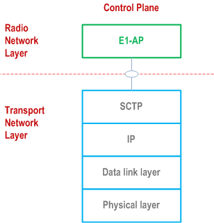
Figure 7.1-1 shows the protocol structure for E1. The TNL is based on IP transport, comprising the SCTP on top of IP. The application layer signalling protocol is referred to as E1AP (E1 Application Protocol).
8 Other E1 interface specifications p. 11
This clause contains the description of the other related 3GPP specifications.
8.1 E1 interface: layer 1 (3GPP TS 37.481) p. 11
3GPP TS 37.481 specifies the physical layer technologies that may be used to support the E1 interface.
8.2 E1 interface: signalling transport (3GPP TS 37.482) p. 11
3GPP TS 37.482 specifies the signalling bearers for the E1AP for the E1 interface.
8.3 E1 interface: E1AP specification (3GPP TS 37.483) p. 12
3GPP TS 37.483 specifies the E1AP protocol for radio network control plane signalling over the E1 interface.
$ Change history p. 13
![]()
![]()