Content for TS 38.401 Word version: 18.2.0
1…
5…
6…
6.1.4
6.1.5…
6.2…
7…
8…
8.2…
8.2.1.4…
8.2.2…
8.2.3…
8.2.4
8.2.5
8.3…
8.4…
8.4.4…
8.5…
8.9…
8.9.4…
8.9.6…
8.9.7…
8.10
8.11…
8.12…
8.13…
8.14…
8.15…
8.15.2…
8.16…
8.17…
8.17.3…
8.17.4
8.18…
8.19…
8.19.2
8.19.3
8.19.4…
8.21…
8.22…
8.23…
8.24…
9…
A…
8.2.1.4 Intra-gNB-DU LTM |R18| p. 35
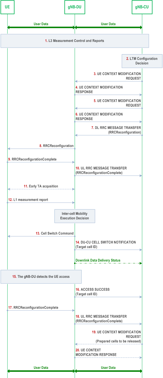
This procedure is used for the case when the UE moves within the same gNB-DU during NR operation for LTM. Figure 8.2.1.4-1 shows the intra-gNB-DU LTM procedure for intra-NR.

Step 1.
The UE sends a MeasurementReport message (L3 measurement result) to the gNB-DU containing measurements of neighbouring cells. The gNB-DU sends an UL RRC MESSAGE TRANSFER message conveying the received MeasurementReport message to the gNB-CU.
Step 2.
The gNB-CU determines to initiate LTM configuration.
Step 3.
The gNB-CU sends a UE CONTEXT MODIFICATION REQUEST message to the gNB-DU for each candidate cell, containing one candidate cell ID and the CSI resource configuration for subsequent LTM. The gNB-CU may provide the LTM configuration ID mapping list to the gNB-DU. The gNB-CU may request PRACH resources from the gNB-DU. The gNB-CU may request the gNB-DU to provide the lower layer configuration for the purpose of generating the reference configuration or provide the lower layer reference configuration to the gNB-DU.
Step 4.
If the gNB-DU accepts the request of LTM configuration, it responds with a UE CONTEXT MODIFICATION RESPONSE message including the generated lower layer RRC configurations for the accepted candidate cell.
Step 5.
The gNB-CU sends a UE CONTEXT MODIFICATION REQUEST message to the gNB-DU which may include the LTM configuration ID mapping list and/or the updated CSI resource configuration.
Step 6.
The gNB-DU responds with a UE CONTEXT MODIFICATION RESPONSE message which includes an updated lower layer configuration, e.g., containing the updated CSI report configuration of the source cell.
Step 7.
The gNB-CU sends a DL RRC MESSAGE TRANSFER message to the gNB-DU, which includes the generated RRCReconfiguration message with the LTM configuration.
Step 8.
The gNB-DU forwards the received RRCReconfiguration message to the UE.
Step 9.
The UE responds to the gNB-DU with an RRCReconfigurationComplete message.
Step 10.
The gNB-DU forwards the RRCReconfigurationComplete message to the gNB-CU via an UL RRC MESSAGE TRANSFER message.
Step 11.
Early synchronization to the candidate cell(s) may be performed as specified in TS 38.300.
Step 12.
The UE sends the L1 measurement result to the gNB-DU. The gNB-DU decides to execute LTM.
Step 13.
The gNB-DU sends the Cell Switch Command to the UE.
Step 14.
The gNB-DU sends the DU-CU CELL SWITCH NOTIFICATION message to the gNB-CU to indicate the initiation of the Cell Switch Command to the UE including the target cell ID.
Step 15.
The gNB-DU detects the UE access in the target cell as specified in TS 38.300.
Step 16.
The gNB-DU sends the ACCESS SUCCESS message to the gNB-CU with the target cell ID.
Step 17.
The UE sends an RRCReconfigurationComplete message to the gNB-DU.
Step 18.
The gNB-DU forwards the RRCReconfigurationComplete message to the gNB-CU via an UL RRC MESSAGE TRANSFER message.
Step 19.
The gNB-CU may send the UE CONTEXT MODIFICATION REQUEST message to the gNB-DU to release the resources of prepared cells.
Step 20.
The gNB-DU responds with a UE CONTEXT MODIFICATION RESPONSE message.
8.2.1.5 Inter-gNB-DU LTM |R18| p. 37
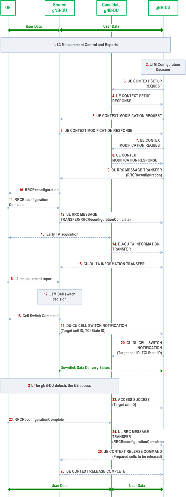
This procedure is used for the case when the UE moves from one gNB-DU to another gNB-DU within the same gNB-CU during NR operation for LTM. Figure 8.2.1.5-1 shows the inter-gNB-DU LTM procedure for intra-NR.

Step 1.
The UE sends a MeasurementReport message (L3 measurement result) to the source gNB-DU containing measurements of neighbouring cells. The source gNB-DU sends an UL RRC MESSAGE TRANSFER message conveying the received MeasurementReport message to the gNB-CU.
Step 2.
The gNB-CU determines to initiate LTM configuration.
Step 3.
The gNB-CU sends a UE CONTEXT SETUP REQUEST message to the candidate gNB-DU(s) for each candidate cell, containing one candidate cell ID and the CSI resource configuration for subsequent LTM. The gNB-CU may provide the LTM configuration ID mapping list to the candidate gNB-DU(s). The gNB-CU may request PRACH resources from the candidate gNB-DU(s). The gNB-CU may request the candidate gNB-DU(s) to provide the lower layer configuration for the purpose of generating the reference configuration or provide the lower layer reference configuration to the candidate gNB-DU(s).
Step 4.
If the candidate gNB-DU accepts the request of LTM configuration, it responds with a UE CONTEXT SETUP RESPONSE message including the generated lower layer RRC configurations for the accepted target candidate cell.
Step 5.
The gNB-CU sends a UE CONTEXT MODIFICATION REQUEST message to the source gNB-DU including the information related to early sync and the LTM configuration ID mapping list for the accepted target candidate cell(s). The gNB-CU may send the updated CSI resource configuration to the source gNB-DU.
Step 6.
The source gNB-DU responds with a UE CONTEXT MODIFICATION RESPONSE message which includes an updated lower layer configuration, e.g., containing the updated CSI report configuration of the source cell.
Step 7.
The gNB-CU may send a UE CONTEXT MODIFICATION REQUEST message to the candidate gNB-DU(s) containing the information for subsequent LTM or for updating the configurations of candidate cells. The gNB-CU may also provide the lower layer part of the reference configuration to the candidate gNB-DU(s).
Step 8.
The candidate gNB-DU responds with a UE CONTEXT MODIFICATION RESPONSE message including the updated lower layer configuration (e.g., the updated CSI report configuration).
Step 9.
The gNB-CU sends a DL RRC MESSAGE TRANSFER message to the source gNB-DU, which includes the generated RRCReconfiguration message with the LTM configuration.
Step 10.
The source gNB-DU forwards the received RRCReconfiguration message to the UE.
Step 11.
The UE responds to the source gNB-DU with an RRCReconfigurationComplete message.
Step 12.
The source gNB-DU forwards the RRCReconfigurationComplete message to the gNB-CU via an UL RRC MESSAGE TRANSFER message.
Step 13.
Early synchronization to the candidate cell(s) may be performed as specified in TS 38.300.
Step 14.
The candidate gNB-DU sends a DU-CU TA INFORMATION TRANSFER message to the gNB-CU, which includes the TA value, the associated PRACH resource information, and etc.
Step 15.
The gNB-CU forwards the TA value, and the associated PRACH resource information to the source gNB-DU in the CU-DU TA INFORMATION TRANSFER message.
Step 16.
The UE sends the L1 measurement result to the source gNB-DU.
Step 17.
The source gNB-DU decides to execute LTM to a target cell.
Step 18.
The source gNB-DU sends the Cell Switch Command to the UE.
Step 19.
The source gNB-DU sends the DU-CU CELL SWITCH NOTIFICATION message to the gNB-CU to indicate the initiation of the Cell Switch Command to the UE including the target cell ID, the TCI state ID(s), and the TA values for subsequent LTM.
Step 20.
The gNB-CU forwards the target cell ID, the TCI state ID(s), and the TA values for subsequent LTM to the target gNB-DU in the CU-DU CELL SWITCH NOTIFICATION message.
Step 21.
The target gNB-DU detects the UE access as specified in TS 38.300.
Step 22.
The target gNB-DU sends the ACCESS SUCCESS message to the gNB-CU with the target cell ID.
Step 23.
The UE sends an RRCReconfigurationComplete message to the target gNB-DU.
Step 24.
The target gNB-DU forwards the RRCReconfigurationComplete message to the gNB-CU via an UL RRC MESSAGE TRANSFER message.
Step 25.
The gNB-CU may send the UE CONTEXT RELEASE COMMAND message to the source gNB-DU to release the resources of prepared cells.
Step 26.
The source gNB-DU responds with a UE CONTEXT RELEASE COMPLETE message.
8.2.1.6 LTM with gNB-CU-UP change |R18| p. 40
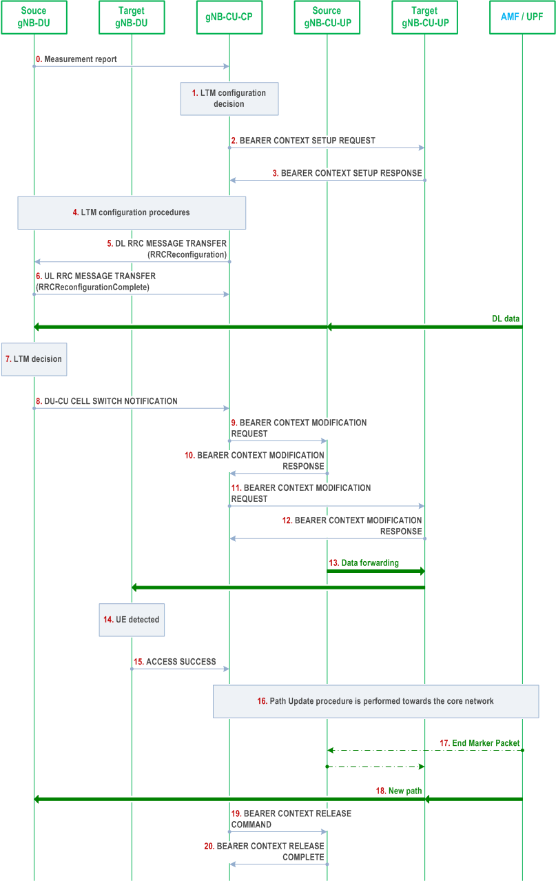
Figure 8.2.1.6-1 shows the procedure used for LTM with the change of gNB-CU-UP within a gNB.

Step 0.
The source gNB-DU forwards the Measurement Report to the gNB-CU-CP.
Step 1.
The gNB-CU-CP decides to initiate LTM configuration.
Step 2.
The gNB-CU-CP sends a BEARER CONTEXT SETUP REQUEST message containing UL TNL address information for NG-U to setup the bearer context in the target gNB-CU-UP.
Step 3.
The target gNB-CU-UP responds with a BEARER CONTEXT SETUP RESPONSE message containing the UL TNL address information for F1-U, DL TNL address information for NG-U, and the TNL address information for data forwarding to the target gNB-CU-UP.
Step 4.
LTM configuration procedures are performed between gNB-CU and candidate gNB-DUs, and between gNB-CU and source gNB-DU as specified from step 3 to step 8 in clause 8.2.1.5.
Step 5-6.
The gNB-CU-CP sends the RRC Reconfiguration message to the source gNB-DU via DL RRC MESSAGE TRANSFER message, and receives the the RRCReconfigurationComplete message from the source gNB-DU via UL RRC MESSAGE TRANSFER message.
Step 7.
The UE sends the lower layer measurement result to the source gNB-DU, and the source gNB-DU decides to execute LTM to a target cell.
Step 8.
The source gNB-DU sends the DU-CU CELL SWITCH NOTIFICATION message to the gNB-CU-CP with the selected target cell ID.
Step 9.
The gNB-CU-CP forwards the selected target cell ID to the target gNB-DU in the CU-DU CELL SWITCH NOTIFICATION message.
Step 10-11.
The gNB-CU-CP may perform the Bearer Context Modification procedure to retrieve the PDCP UL/DL status and to exchange the TNL address information for data forwarding for the bearers to the source gNB-CU-UP.
Step 12-13.
The gNB-CU-CP performs the Bearer Context Modification procedure to send the DL TNL address information for F1-U and the PDCP UL/DL status to the target gNB-CU-UP.
Step 14.
Data Forwarding may be performed from the source gNB-CU-UP to the target gNB-CU-UP.
Step 15.
The target gNB-DU detects the UE in the target cell.
Step 16.
The target gNB-DU sends an ACCESS SUCCESS message to the gNB-CU-CP.
Step 17-19.
Path Switch procedure is performed to update the DL TNL address information for the NG-U towards the core network.
Step 20-21.
Bearer Context Release procedure may be performed to release the UE context in the source gNB-CU-UP.