Content for TS 24.501 Word version: 18.7.0
1…
3…
4…
4.4…
4.4.3…
4.5…
4.5.3…
4.6…
4.7…
4.9…
4.15…
5…
5.2…
5.3…
5.3.2…
5.3.7…
5.3.19…
5.4…
5.4.1.3…
5.4.2…
5.4.4…
5.4.5…
5.4.6…
5.5…
5.5.1.2.4
5.5.1.2.5…
5.5.1.3…
5.5.1.3.4
5.5.1.3.5…
5.5.2…
5.6…
5.6.2…
6…
6.1.4…
6.2…
6.3…
6.3.2…
6.3.3…
6.4…
6.4.1.4…
6.4.2…
6.5…
7…
8…
8.2.9…
8.3…
9…
9.11.2…
9.11.2.10…
9.11.3…
9.11.3.4…
9.11.3.8…
9.11.3.14…
9.11.3.18C…
9.11.3.29…
9.11.3.33…
9.11.3.39…
9.11.3.45…
9.11.3.50…
9.11.3.53A…
9.11.3.68…
9.11.3.75…
9.11.4…
9.11.4.10…
9.11.4.13…
9.11.4.16…
9.11.4.30…
9.12
10…
A…
B…
C…
D…
D.6…
D.6.3…
D.6.8
D.7…
9.11.4.30 Requested MBS container
9.11.4.31 Received MBS container
9.11.4.32 PDU session pair ID
9.11.4.33 RSN
9.11.4.34 ECS address
9.11.4.36 N3QAI
9.11.4.37 Non-3GPP delay budget
9.11.4.38 URSP rule enforcement reports
9.11.4.39 Protocol description
...
...
9.11.4.30 Requested MBS container |R17| p. 1048
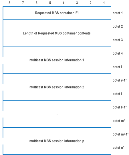
The purpose of the Requested MBS container information element is for UE to request to join or leave one or more multicast MBS sessions.
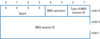
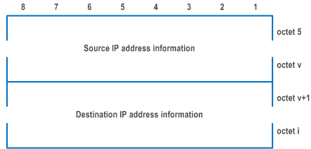
The Requested MBS container information element is coded as shown in Figure 9.11.4.30.1, Figure 9.11.4.30.2, Figure 9.11.4.30.3, Figure 9.11.4.30.4 and Table 9.11.4.30.1.
The Requested MBS container is a type 6 information element with a minimum length of 8 octets and a maximum length of 65538 octets.

| Type of multicast MBS session ID (bits 1 to 2 of octet 4) | |
| Bits
2 1 | |
| 0 1 | Temporary Mobile Group Identity (TMGI) |
| 1 0 | Source specific IP multicast address for IPv4 |
| 1 1 | Source specific IP multicast address for IPv6 |
| All other values are reserved. Bits 3 to 8 of octet 3 are spare and shall be coded as zero. | |
| MBS operation (bits 3 to 4 of octet 4) | |
| Bits
4 3 | |
| 0 1 | Join multicast MBS session |
| 1 0 | Leave multicast MBS session |
| All other values are reserved. Bits 5 to 8 of octet 4 are spare and shall be coded as zero. If Type of multicast MBS session ID is set to "Temporary Mobile Group Identity (TMGI)", the multicast MBS session ID contains the TMGI (octet 5 to i) and is coded as described in subclause 10.5.6.13 of TS 24.008 starting from octet 2. The structure of the TMGI is defined in TS 23.003. If Type of multicast MBS session ID is set to "Source specific IP multicast address for IPv4" or "Source specific IP multicast address for IPv6", the MBS session ID contains the Source IP address information and the Destination IP address information. | |
| Source IP address information (octet 5 to v) | |
| This field contains the IP unicast address used as source address in IP packets for identifying the source of the multicast service. If the type of multicast MBS session ID indicates "Source specific IP multicast address for IPv4", the Source IP address information in octet 5 to octet 8 contains an IPv4 address. If the type of multicast MBS session ID indicates "Source specific IP multicast address for IPv6", the Source IP address information in octet 5 to octet 20 contains an IPv6 address. | |
| Destination IP address information (octet v+1 to i) | |
| This field contains the IP multicast address used as destination address in related IP packets for identifying a multicast service associated with the source. If the type of multicast MBS session ID indicates "Source specific IP multicast address for IPv4", the Destination IP address information in octet v+1 to octet v+4 contains an IPv4 address. If the type of multicast MBS session ID indicates "Source specific IP multicast address for IPv6", the Source IP address information in octet v+1 to octet v+16 contains an IPv6 address. | |
9.11.4.31 Received MBS container |R17| p. 1050
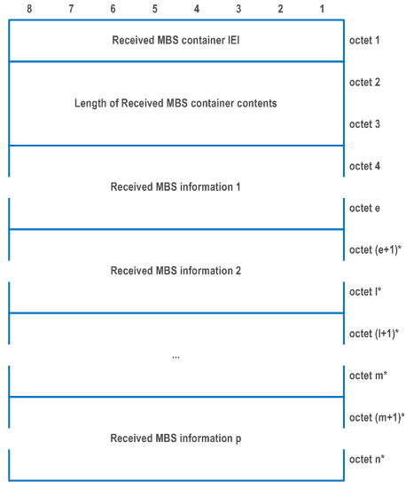
The purpose of the Received MBS container information element is to indicate to the UE the information of the multicast MBS sessions that the network accepts or rejects the UE to join, the information of the multicast MBS sessions that the UE is removed from, or the information of the updated MBS service area.
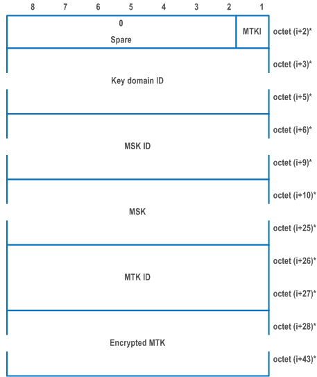
The Received MBS container information element is coded as shown in Figure 9.11.4.31.1, Figure 9.11.4.31.2, Figure 9.11.4.31.3, Figure 9.11.4.31.4, Figure 9.11.4.31.5, Figure 9.11.4.31.6, Figure 9.11.4.31.7, Figure 9.11.4.31.8, Figure 9.11.4.31.9, Figure 9.11.4.31.10, Figure 9.11.4.31.11 and Table 9.11.4.31.1.
The Received MBS container is a type 6 information element with a minimum length of 9 octets and a maximum length of 65538 octets.
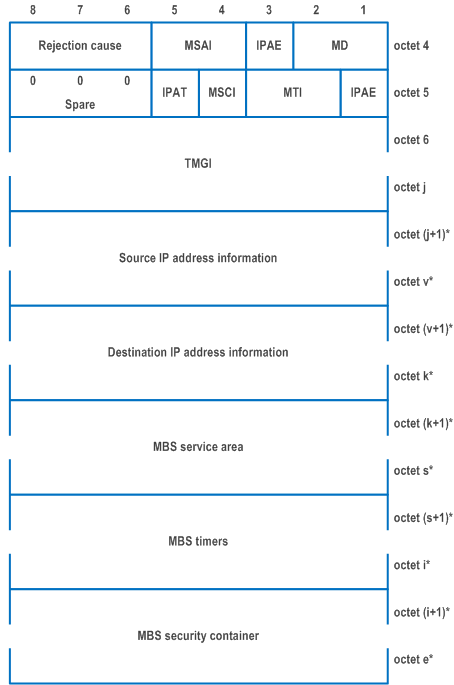




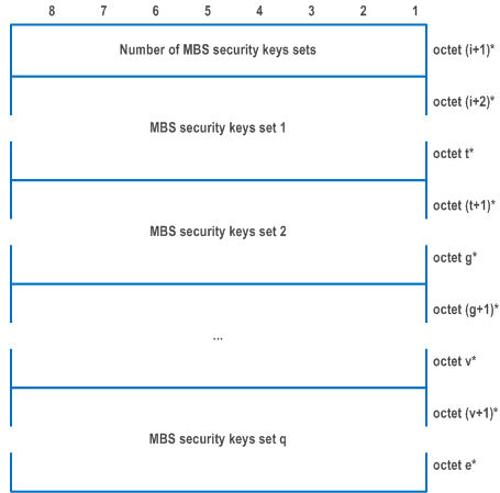
| MBS decision (MD) (bits 1 to 3 of octet 4) | |
| The MD indicates the network decision of the join requested by the UE, the network requests to remove the UE from the multicast MBS session or the network request to update the MBS service area or the security information of multicast MBS session | |
| Bits
3 2 1 | |
| 0 0 1 | MBS service area update |
| 0 1 0 | MBS join is accepted |
| 0 1 1 | MBS join is rejected |
| 1 0 0 | Remove UE from multicast MBS session |
| 1 0 1 | MBS security information update |
| All other values are unused in this version of the specification and interpreted as 000 if received. | |
| If MD is set to "MBS join is rejected" or "Remove UE from multicast MBS session", bits 6 to 8 of octet 4 shall contain the Rejection cause which indicates the reason of rejecting the MBS join request or the reason of removing the UE from multicast MBS session, respectively, otherwise bits 6 to 8 of octet 4 are spare and shall be coded as zero. | |
| MBS service area indication (MSAI) (bits 4 and 5 of octet 4) | |
| The MSAI indicates whether and how the MBS service area is included in the IE. | |
| Bits
5 4 | |
| 0 0 | MBS service area not included |
| 0 1 | MBS service area included as MBS TAI list |
| 1 0 | MBS service area included as NR CGI list |
| 1 1 | MBS service area included as MBS TAI list and NR CGI list |
| Rejection cause (bits 6 to 8 of octet 4) | |
| The Rejection cause indicates the reason of rejecting the join request or the reason of removing the UE from the MBS session. | |
| Bits
8 7 6 | |
| 0 0 0 | No additional information provided |
| 0 0 1 | Insufficient resources |
| 0 1 0 | User is not authorized to use MBS service |
| 0 1 1 | multicast MBS session has not started or will not start soon |
| 1 0 0 | User is outside of local MBS service area |
| 1 0 1 | Session context not found |
| 1 1 0 | multicast MBS session is released |
| All other values are unused in this version of the specification and interpreted as 000 if received. | |
| IP address existence (IPAE) (bit1 of octet 5) | |
| The IPAE indicates whether the Source IP address information and Destination IP address information are included in the IE or not. | |
| Bit
1 | |
| 0 | Source and destination IP address information not included |
| 1 | Source and destination IP address information included |
| If IPAE is set to "Source and destination IP address information included", Source IP address information and Destination IP address information shall be included in the IE, otherwise Source IP address information and Destination IP address information shall not be included in the IE (NOTE 1). | |
| MBS timer indication (MTI) (bits 2 and 3 of octet 5) | |
| The MTI indicates whether there is MBS timer included in the IE or not. | |
| Bits
3 2 | |
| 0 0 | No MBS timers included |
| 0 1 | MBS start time included |
| 1 0 | MBS back-off timer included |
| All other values are unused in this version of the specification and interpreted as 00 if received | |
| MBS security container indication (MSCI) (bit 4 of octet 5) | |
| The MSCI indicates whether the MBS security container is included in the IE or not | |
| Bit
4 | |
| 0 | MBS security container not included |
| 1 | MBS security container included |
| IP address type (IPAT) (bit 5 of octet 5) | |
| The IPAT indicates the type of the source IP address information and destination IP address information. This field is ignored when IPAE is set to "Source and destination IP address information not included". | |
| Bit
5 | |
| 0 | Source IP address information and destination IP address information are IPv4 |
| 1 | Source IP address information and destination IP address information are IPv6 |
| Bits 6 to 8 of octet 5 are spare and shall be coded as zero. | |
| TMGI (octets 6 to j) | |
| The TMGI is coded as described in subclause 10.5.6.13 of TS 24.008 starting from octet 2. The structure of the TMGI is defined in TS 23.003. | |
| Source IP address information (octet j+1 to v) | |
| This field contains the IP unicast address used as source address in IP packets for identifying the source of the multicast service. The value of this field is copied from the corresponding source IP address information in the requested MBS container. If the IPAT indicates "Source and destination IP address information are IPv4", the Source IP address information in octet j+1 to octet j+4 contains an IPv4 address. If the IPAT indicates "Source and destination IP address information are IPv6", the Source IP address information in octet j+1 to octet j+16 contains an IPv6 address. | |
| Destination IP address information (octet v+1 to k) | |
| This field contains the IP multicast address used as destination address in related IP packets for identifying a multicast service associated with the source. The value of this field is copied from the corresponding destination IP address information in the requested MBS container. If the IPAT indicates "Source and destination IP address information are IPv4", the Destination IP address information in octet v+1 to octet v+4 contains an IPv4 address. If the IPAT indicates "Source and destination IP address information are IPv6", the Destination IP address information in octet v+1 to octet v+16 contains an IPv6 address. | |
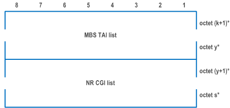
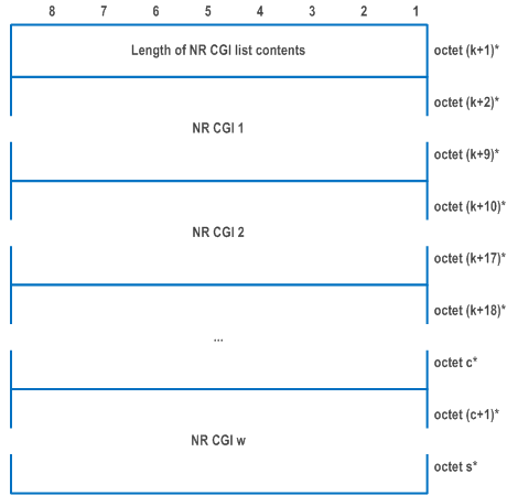
| MBS service area (octet k+1 to s) | |
| The MBS service area contains the MBS TAI list, the NR CGI list or both, that identifies the service area(s) for a local MBS service. | |
| MBS TAI list (octet k+1 to s) | |
| The MBS TAI list is coded as octet 2 and above of the 5GS tracking area identity list IE defined in subclause 9.11.3.9. | |
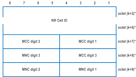
| NR CGI (octet k+2 to k+9) | |
| The NR CGI globally identifies an NR cell. It contains the NR Cell ID and the PLMN ID of that cell. | |
| NR Cell ID (octet k+2 to k+6) | |
| The NR Cell ID consists of 36 bits identifying an NR Cell ID as specified in subclause 9.3.1.7 of TS 38.413, in hexadecimal representation. Bit 8 of octet k+2 is the most significant bit and bit 5 of octet k+6 is the least significant bit. Bits 1 to 4 of octet k+6 are spare and shall be coded as zero. | |
| MCC, Mobile country code (octet k+7 and bits 1 to 4 octet k+8) | |
| The MCC field is coded as in ITU-T Recommendation E.212 [42], Annex A. | |
| MNC, Mobile network code (bits 5 to 8 of octet k+8 and octet k+9) | |
| The coding of this field is the responsibility of each administration but BCD coding shall be used. The MNC shall consist of 2 or 3 digits. If a network operator decides to use only two digits in the MNC, bits 5 to 8 of octet k+8 shall be coded as "1111". | |
| The MCC and MNC digits are coded as octets 6 to 8 of the Temporary mobile group identity IE in Figure 10.5.154 of TS 24.008. | |
| MBS start time (octets s+1 to s+6) | |
| The MBS start time is coded as described in subclause 10.5.3.9 in TS 24.008 starting from octet 2 till octet 7. | |
| MBS back-off timer (octet s+1) | |
| The MBS back-off timer is coded as octet 3 described in subclause 10.5.7.4a in TS 24.008. | |
| MTK indication (MTKI) (bit 1 of octet i+2) | |
| The MTKI indicates whether the MTK ID and Encrypted MTK are included in the MBS security keys set or not. | |
| Bit
1 | |
| 0 | MTK ID and Encrypted MTK not included |
| 1 | MTK ID and Encrypted MTK included |
| Bits 2 to 8 of octet i+2 are spare and shall be coded as zero | |
| Key domain ID (octet i+3 to i+5) | |
| The key domain ID is 3 bytes long and is defined in TS 33.246 (NOTE 2). | |
| MBS Service Key Identifier (MSK ID) (octets i+6 to i+9) | |
| The MSK ID is 4 bytes long and is defined in TS 33.246. | |
| MBS Service Key (MSK) (octets i+10 to i+25) | |
| The MSK is 16 bytes long and is defined in TS 33.246. | |
| MBS Traffic Key Identifier (MTK ID) (octets i+26 to i+27) | |
| The MTK ID is 2 bytes long and is defined in TS 33.246. | |
| Encrypted MBS Traffic Key (Encrypted MTK) (octets i+28 to i+43) | |
| The Encrypted MTK is 16 bytes long and contains the encrypted version of MTK using MSK as defined in TS 33.246. | |
|
NOTE 1:
The IPAE bit is not expected to be set to "Source and destination IP address information included" when the MBS decision (MD) indicates "Remove UE from multicast MBS session".
NOTE 2:
|
|
9.11.4.32 PDU session pair ID |R17| p. 1057
The purpose of the PDU session pair ID information element is to indicate a PDU session pair ID.
The PDU session pair ID information element is coded as shown in Figure 9.11.4.32.1 and Table 9.11.4.32.1.
The PDU session pair ID is a type 4 information element with a length of 3 octets.
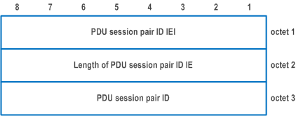
| PDU session pair ID (octet 3) | |
| Bits
8 7 6 5 4 3 2 1 | |
| 0 0 0 0 0 0 0 0 | PDU session pair ID 0 |
| to | to |
| 0 0 0 0 0 1 1 0 | PDU session pair ID 6 |
| All other values are reserved. | |
9.11.4.33 RSN |R17| p. 1058
The purpose of the RSN information element is to indicate an RSN.
The RSN information element is coded as shown in Figure 9.11.4.33.1 and Table 9.11.4.33.1.
The RSN is a type 4 information element with a length of 3 octets.
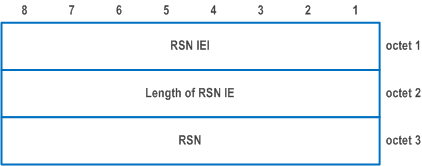
| RSN (octet 3) | |
| Bits
8 7 6 5 4 3 2 1 | |
| 0 0 0 0 0 0 0 0 | v1 |
| 0 0 0 0 0 0 0 1 | v2 |
| All other values are spare and shall not be used by a UE compliant to the present version of this specification. | |
9.11.4.34 ECS address |R17| p. 1058
The purpose of the ECS address information element is to indicate the ECS address (either IPv4 address, IPv6 address, or FQDN) and the associated spatial validity condition.
The ECS address information element is coded as shown in Figure 9.11.4.34.1, Figure 9.11.4.34.2, Table 9.11.4.34.1, and Table 9.11.4.34.2.
The ECS address information element is a type 6 information element with minimum length of 8 octets and a maximum length of 65538 octets.


| Type of ECS address (octet 4, bit 1 to 4) | |
| Bits
4 3 2 1 | |
| 0 0 0 0 | IPv4 |
| 0 0 0 1 | IPv6 |
| 0 0 1 0 | FQDN |
| 1 1 1 1 | Unspecified |
| All other values are spare. The receiving entity shall ignore an ECS address IE with type of ECS address containing a spare value. | |
| Type of spatial validity condition (octet 4, bit 5 to 8) | |
| Bits
8 7 6 5 | |
| 0 0 0 0 | No spatial validity condition |
| 0 0 0 1 | Geographical service area |
| 0 0 1 0 | Tracking area |
| 0 0 1 1 | Country-wide |
| All other values are spare. The receiving entity shall ignore a spatial validity condition with type of spatial validity condition containing an unknown value. | |
| If the type of ECS address indicates IPv4, then the ECS address field contains an IPv4 address in octet 5 to octet 8. | |
| If the type of ECS address indicates IPv6, then the ECS address field contains an IPv6 address in octet 5 to octet 20 and is encoded according to RFC 4291. | |
| If the type of ECS address indicates FQDN, then the ECS address field contains in octet 5 the length of FQDN value and in octet 6 to octet a an FQDN value encoded as defined in subclause 19.4.2 in TS 23.003. | |
| If the type of ECS address indicates unspecified, then the remaining fields of ECS address information element shall be passed to the upper layers. | |
| Spatial validity condition contents (octet (a+1)* to n*) | |
| The spatial validity condition contents contain a variable number of spatial validity condition information. | |
| ECS authentication methods indicator (EAMI) (octet n+1, bit 1) | |
| 0 | ECS authentication methods field is not included |
| 1 | ECS authentication methods field is included |
| If the EAMI bit is set to "ECS authentication methods field is included" then the ECS authentication methods field is included otherwise the ECS authentication methods field is not included. ECS authentication methods is an optional field and is included based on operator requirements. | |
| If the type of spatial validity condition of the ECS address indicates No spatial validity condition, then the spatial validity condition information field is empty. | |
| If the type of spatial validity condition of the ECS address indicates geographical service area, then the spatial validity condition information field contains a geographical service area which is specified by geographical descriptions as defined in TS 23.032. | |
| If the type of spatial validity condition of the ECS address indicates tracking area, then the spatial validity condition information field contains a TAI as defined in subclause 9.11.3.8 starting from octet 2. | |
| If the type of spatial validity condition of the ECS address indicates country-wide, then the spatial validity condition information field contains an MCC as defined in in ITU-T Recommendation E.212 [42], Annex A. The first MCC digit is coded in bit 1 to 4 of the octet b, the second MCC digit is coded in bit 5 to 8 of the octet b, and the third MCC digit is coded in bit 1 to 4 of the octet b+1. Bit 5 to bit 8 of the octet b+1 shall be padded with 1. If only two digits are used for for MCC, octet b+1 shall be padded with 1. | |
| ECS authentication methods (octet n+2) | |
| TLS client server certificate indicator (TLSCSCI) (octet n+2, bit 1) | |
| 0 | TLS client server certificate not supported |
| 1 | TLS client server certificate supported |
| TLS with AKMA indicator (TLSAI) (octet n+2, bit 2) | |
| 0 | TLS with AKMA not supported |
| 1 | TLS with AKMA supported |
| TLS with GBA indicator (TLSGI) (octet n+2, bit 3) | |
| 0 | TLS with GBA not supported |
| 1 | TLS with GBA supported |
9.11.4.35 Void
9.11.4.36 N3QAI |R18| p. 1061
The purpose of the N3QAI information element is to indicate a set of QoS parameters to be used by the UE for non-3GPP access network resource management behind the UE.
The N3QAI information element is a type 6 information element with a minimum length of 9 octets. The maximum length for the information element is 65538 octets.
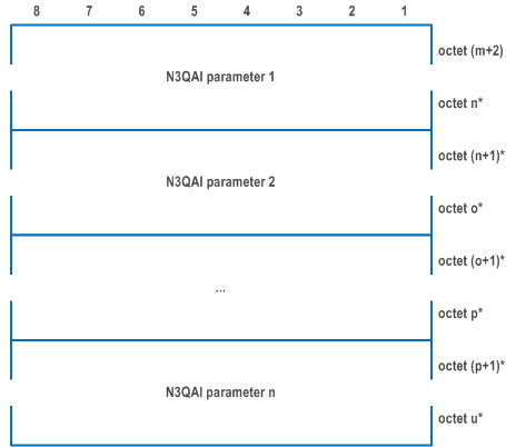
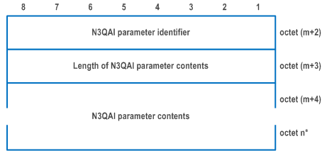
The N3QAI information element is coded as shown in Figure 9.11.4.36.1, Figure 9.11.4.36.2, Figure 9.11.4.36.3, Figure 9.11.4.36.4, and Table 9.11.4.36.1.
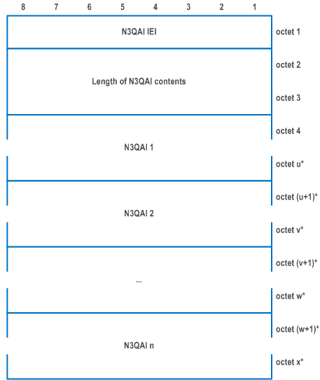
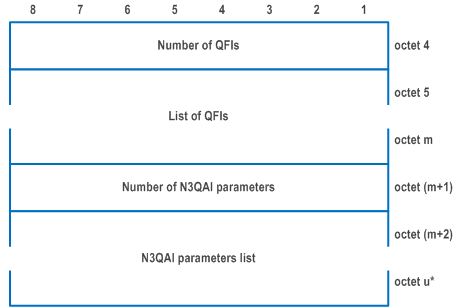
| Number of QFIs (octet 4) | |
| The number of QFIs field contains the binary coding for the number of QFIs associated with the same N3QAI parameters. This field is encoded in bits 8 through 1 of octet 4 where bit 8 is he most significant and bit 1 is the least significant bit. | |
| List of QFIs (octet 5 to octet m) | |
| This field indicates QoS flow(s) associated with the same N3QAI parameters. This field contains QFI values encoded as below: | |
| Bits
8 7 6 5 4 3 2 1 | |
| 0 0 0 0 0 0 0 0 | Reserved |
| 0 0 0 0 0 0 0 1 | QFI 1 |
| to | |
| 0 0 1 1 1 1 1 1 | QFI 63 |
| The other values are spare. If spare value is used, the UE shall ignore the value. | |
| Number of N3QAI parameters (bits 8 to 1 of octet (m+1)) | |
| The number of N3QAI parameters field contains the binary coding for the number of N3QAI parameters in the N3QAI parameters list field. The number of N3QAI parameters field is encoded in bits 8 through 1 of octet (m+1) where bit 8 is the most significant and bit 1 is the least significant bit. | |
| N3QAI parameters list (octets (m+2) to q*) | |
| The N3QAI parameters list field contains a variable number of N3QAI parameters. | |
Each N3QAI parameter included in the N3QAI parameters list is of variable length and consists of:
| |
The N3QAI parameter identifier field is used to identify each parameter included in the N3QAI parameters list and it contains the hexadecimal coding of the parameter identifier. Bit 8 of the parameter identifier field contains the most significant bit and bit 1 contains the least significant bit. In this version of the protocol, the following parameter identifiers are specified:
| |
| If the N3QAI parameters list contains a N3QAI parameter identifier that is not supported by the receiving entity, the corresponding parameter shall be discarded. The length of N3QAI parameter contents field contains the binary coded representation of the length of the parameter contents field. The first bit in transmission order is the most significant bit. | |
| For the N3QAI parameter identifiers indicating "5QI", "GFBR uplink", "GFBR downlink", "MFBR uplink", "MFBR downlink", and "Averaging window", the format of the N3QAI parameter contents follows the Table 9.11.4.12.1 of subclause 9.11.4.12 of this specification. | |
| For the N3QAI parameter identifiers indicating "Resource type", "Priority level", "Packet delay budget", "Packet error rate", "Maximum data burst volume", "Maximum packet loss rate downlink", and "Maximum packet loss rate uplink", the format of the N3QAI parameter contents follows the Table 9.3.1.1-2 of subclause 9.3.1.1 of TS 24.502. | |
| When the N3QAI parameter identifier indicates "ARP", the N3QAI parameter contents field contains the binary representation of ARP that is one octet in length. The range of the ARP priority level is 1 to 15 with 1 as the highest priority as specified in subclause 5.7.2.2 of TS 23.501. | |
| When the N3QAI parameter identifier indicates "Periodicity", the N3QAI parameter contents field contains the binary representation of the periodicity for the traffic with a unit of microsecond. (NOTE 1) | |
|
NOTE:
The periodicity refers to the time interval between start of two data bursts for supporting consumer real time applications e.g., XR.
|
|
9.11.4.37 Non-3GPP delay budget |R18| p. 1065
The purpose of the Non-3GPP delay budget information element is to indicate the non-3GPP delay budget for the non-3GPP network behind the UE to the network.
The Non-3GPP delay budget information element is a type 6 information element with a minimum length of 8 octets. The maximum length for the information element is 65538 octets.
The Non-3GPP delay budget information element is coded as shown in Figure 9.11.4.37.1.
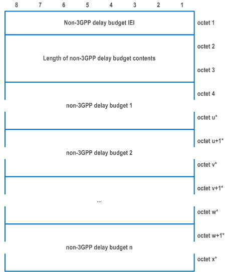
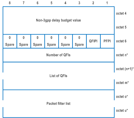
| The Non-3GPP delay budget value field contains the binary representation of the Non-3GPP delay budget in units of 0.5ms. | |
| Bits
8 7 6 5 4 3 2 1 8 7 6 5 4 3 2 1 | |
| 0 0 0 0 0 0 0 0 0 0 0 0 0 0 0 0 | |
| thru | |
| 1 1 1 1 1 1 1 1 1 1 1 1 1 1 1 1 | |
| Packet filter presence indicator (PFPI) (bit 1 of octet 6) | |
| 0 | Packet filter list associated with the Non-3GPP delay budget value is not present |
| 1 | Packet filter list associated with the Non-3GPP delay budget value is present |
| QoS flow identifier presence indicator (QFIPI) (bit 2 of octet 6) | |
| 0 | QoS flow identifier associated with the Non-3GPP delay budget value is not present |
| 1 | QoS flow identifier associated with the Non-3GPP delay budget value is present |
| Number of QFIs (octet n*) | |
| The number of QFIs field is present if QFIPI is set to 1. If QFIPI is not set to 1, this field shall not be included in the non-3GPP delay budget. The number of QFIs field contains the binary coding for the number of QFIs associated with the same non-3GPP delay budget value. This field is encoded in bits 8 through 1 of octet 4 where bit 8 is he most significant and bit 1 is the least significant bit. | |
| List of QFIs (octet (n+1)* to octet m*) | |
| The list of QFIs field is present if QFIPI is set to 1. If QFIPI is not set to 1, this field shall not be included in the non-3GPP delay budget. This field indicates QoS flow(s) associated with the same non-3GPP delay budget value. This field contains QFI values encoded as below | |
| Bits
8 7 6 5 4 3 2 1 | |
| 0 0 0 0 0 0 0 0 | Reserved |
| 0 0 0 0 0 0 0 1 | QFI 1 |
| to | |
| 0 0 1 1 1 1 1 1 | QFI 63 |
| The other values are spare. If spare value is used, the UE shall ignore the value. | |
| Packet filter list (octet 7 to u) | |
| The packet filter list is present if PFPI is set to 1. If not present, this field shall not be included in the non-3GPP delay budget. The encoding of the packet filter list follows the Figure 9.11.4.13.4 and the Table 9.11.4.13.1. | |
9.11.4.38 URSP rule enforcement reports |R18| p. 1067
The purpose of the URSP rule enforcement reports information element is to provide one or more URSP rule enforcement reports to the network. Each URSP rule enforcement report includes all the connection capabilities contained in the traffic descriptor of each URSP rule associated to the PDU session.
The URSP rule enforcement reports information element is coded as shown in Figure 9.11.4.38.1, Figure 9.11.4.38.2, and Table 9.11.4.38.1.
The URSP rule enforcement reports is a type 4 information element with a minimum length of 4 octets.


| URSP rule enforcement report (octet 3 to octet a) | |
| The URSP rule enforcement report field contains all the connection capabilities contained in the traffic descriptor of one reported URSP rule. | |
| Number of connection capability identifiers (octet 3) | |
| The number of connection capability identifiers field indicates number of indicated connection capability identifiers in binary representation. The value of this field shall be set to at least one, and the receiving entity shall ignore the URSP rule enforcement reports IE with "Number of connection capability identifiers" field set to zero. | |
| Connection capability identifier | |
| Connection capability identifier is encoded as defined in TS 24.526 Table 5.2.1. | |
9.11.4.39 Protocol description |R18| p. 1068
The purpose of the Protocol description information element is to provide protocol description for UL PDU set handling to the UE.
The Protocol description information element is a type 6 information element with a minimum length of 6 octets.
The Protocol description information element is coded as shown in Figure 9.11.4.39.1, Figure 9.11.4.39.2, Figure 9.11.4.39.3, Figure 9.11.4.39.4, and Table 9.11.4.39.1.


| Length of protocol description (octet 4 and octet 5) (see NOTE 1) | |
| The length of protocol description field indicates the length of the protocol description entry. | |
| QoS Rule Identifier (QRI) (octet 6) | |
| The QoS Rule Identifier (QRI) field contains the QoS rule identifier as specified in subclause 9.11.4.13. Each protocol description entry is associated with the QoS rule identified by the QRI field. | |
| Transport Protocol (octet 7, bits 1 to 4) | |
| The Transport Protocol field indicates the transport protocol used by the media flow, e.g., RTP or SRTP as specified in TS 26.522. | |
| Bits
4 3 2 1 | |
| 0 0 0 1 | RTP |
| 0 0 1 0 | SRTP |
| All other values are spare. | |
| RTP header extension information presence indicator (HEIPI) (bit 5 of octet 7) | |
| The HEIPI field indicates whether the RTP header extension information (RTP header extension type field and RTP header extension id field) is included in the IE or not. | |
| 0 | RTP header extension information not included |
| 1 | RTP header extension information included |
| RTP payload information list presence indicator (PILPI) (bit 6 of octet 7) | |
| The PILPI field indicates whether the RTP payload information list is included in the IE or not. | |
| 0 | RTP payload information list not included |
| 1 | RTP payload information list included |
| RTP header extension type (octet 8) | |
| The RTP header extension type field contains the RTP header extension type, i.e the RTP Header Extension for PDU Set Marking as specified in subclause 4.2 of TS 26.522. | |
| Bits
8 7 6 5 4 3 2 1 | |
| 0 0 0 0 0 0 0 1 | RTP Header Extension for PDU Set Marking |
| All other values are spare. | |
| RTP header extension id (octet 9) | |
| The RTP header extension id field contains the RTP header extension id which is coded as binary representation of an integer between 1 (inclusive) and 255 (inclusive) as defined in RFC 8285. | |
| RTP payload information list (octets 10 to u) (see NOTE 2) | |
| The RTP payload information list contains the RTP payload information for the RTP stream, which can be used to derive the PDU set information. | |
| RTP payload format (octet 12) | |
| Bits
8 7 6 5 4 3 2 1 | |
| 0 0 0 0 0 0 0 1 | RTP payload format for H.264/AVC codec as specified in subclause A.2.2 of TS 26.522 |
| 0 0 0 0 0 0 1 0 | RTP payload format for H.265/HEVC codec as specified in subclause A.2.2 of TS 26.522 |
| All other values are spare and not used. | |
| RTP payload type (octet 14) | |
| The RTP payload type field indicates the RTP or SRTP payload type, it contains the binary representation of an integer between 1(inclusive) and 127(inclusive). The other values are spare. If spare value is used, the UE shall ignore the value. | |
|
NOTE 1:
If the value of the length of protocol description field is set to 1, the protocol description entry is deleted for the associated QoS rule. If the value of the length of protocol description field is greater than 1, the protocol description entry is added or replaced for the associated QoS rule.
NOTE 2:
In this release of the specification, the RTP payload information list contains only one RTP payload information entry.
|
|