Content for TS 24.501 Word version: 18.7.0
1…
3…
4…
4.4…
4.4.3…
4.5…
4.5.3…
4.6…
4.7…
4.9…
4.15…
5…
5.2…
5.3…
5.3.2…
5.3.7…
5.3.19…
5.4…
5.4.1.3…
5.4.2…
5.4.4…
5.4.5…
5.4.6…
5.5…
5.5.1.2.4
5.5.1.2.5…
5.5.1.3…
5.5.1.3.4
5.5.1.3.5…
5.5.2…
5.6…
5.6.2…
6…
6.1.4…
6.2…
6.3…
6.3.2…
6.3.3…
6.4…
6.4.1.4…
6.4.2…
6.5…
7…
8…
8.2.9…
8.3…
9…
9.11.2…
9.11.2.10…
9.11.3…
9.11.3.4…
9.11.3.8…
9.11.3.14…
9.11.3.18C…
9.11.3.29…
9.11.3.33…
9.11.3.39…
9.11.3.45…
9.11.3.50…
9.11.3.53A…
9.11.3.68…
9.11.3.75…
9.11.4…
9.11.4.10…
9.11.4.13…
9.11.4.16…
9.11.4.30…
9.12
10…
A…
B…
C…
D…
D.6…
D.6.3…
D.6.8
D.7…
9.11.3.75 Extended rejected NSSAI
9.11.3.76 UE request type
9.11.3.77 Paging restriction
9.11.3.79 NID
9.11.3.80 PEIPS assistance information
9.11.3.81 5GS additional request result
9.11.3.82 NSSRG information
9.11.3.83 List of PLMNs to be used in disaster condition
9.11.3.84 Registration wait range
9.11.3.85 PLMN identity
9.11.3.86 Extended CAG information list
9.11.3.87 NSAG information
9.11.3.88 ProSe relay transaction identity
9.11.3.89 Relay key request parameters
9.11.3.90 Relay key response parameters
9.11.3.91 Priority indicator
9.11.3.92 SNPN list
9.11.3.93 N3IWF identifier
9.11.3.94 TNAN information
9.11.3.95 RAN timing synchronization
9.11.3.96 Extended LADN information
9.11.3.97 Alternative NSSAI
9.11.3.98 Type 6 IE container
9.11.3.99 Non-3GPP access path switching indication
9.11.3.100 S-NSSAI location validity information
9.11.3.101 S-NSSAI time validity information
9.11.3.102 Non-3GPP path switching information
9.11.3.103 Partial NSSAI
9.11.3.104 AUN3 indication
9.11.3.105 Feature authorization indication
9.11.3.106 Payload container information
9.11.3.107 AUN3 device security key
9.11.3.108 On-demand NSSAI
9.11.3.109 Extended 5GMM cause
...
...
9.11.3.75 Extended rejected NSSAI |R17| p. 969
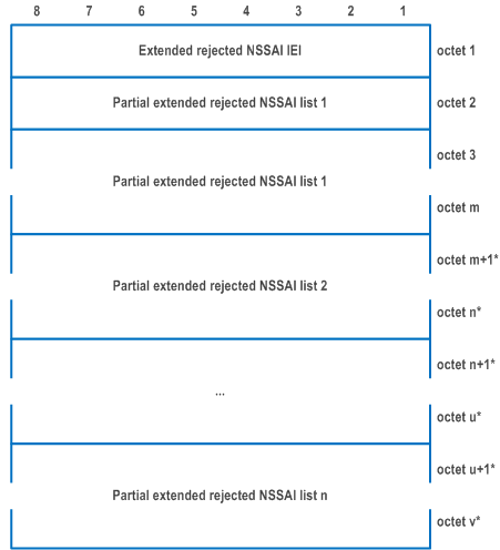
The purpose of the Extended rejected NSSAI information element is to identify a collection of rejected S-NSSAIs if UE supports extended rejected NSSAI.
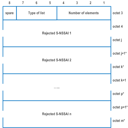
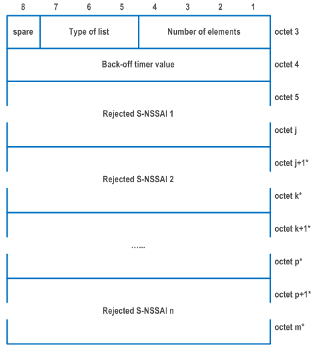
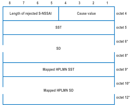
The Extended rejected NSSAI information element is coded as shown in Figure 9.11.3.75.1, Figure 9.11.3.75.2 and Table 9.11.3.75.1.
The Extended rejected NSSAI is a type 4 information element with a minimum length of 5 octets and a maximum length of 90 octets.
| Value part of the Extended rejected NSSAI information element (octet 3 to v) | |
| The value part of the Extended rejected NSSAI information element consists of one or more partial extended rejected NSSAI lists. The length of each partial extended rejected NSSAI list can be determined from the 'type of list' field and the 'number of elements' field in the first octet of the partial extended rejected NSSAI list. Each rejected S-NSSAI consists of one S-NSSAI and an associated cause value. Each rejected S-NSSAI also includes the mapped HPLMN S-NSSAI if available. The length of each rejected S-NSSAI can be determined by the 'length of rejected S-NSSAI' field in the first octet of the rejected S-NSSAI. The UE shall store the complete list received (NOTE 0). If more than 8 rejected S-NSSAIs are included in this information element, the UE shall store the first 8 rejected S-NSSAIs and ignore the remaining octets of the information element. | |
| Partial extended rejected NSSAI list: | |
| Number of elements (octet 3, bits 1 to 4) | |
| Bits
4 3 2 1 | |
| 0 0 0 0 | 1 element |
| 0 0 0 1 | 2 element |
| … | |
| 0 1 1 0 | 7 element |
| 0 1 1 1 | 8 element |
| All other values are unused and shall be interpreted as 8, if received by the UE. | |
| Type of list (octet 3, bits 5 to 7) (NOTE 7) | |
| Bits
7 6 5 | |
| 0 0 0 | list of S-NSSAIs without any associated back-off timer value |
| 0 0 1 | list of S-NSSAIs with one associated back-off timer value that applies to all S-NSSAIs in the list |
| All other values are reserved. Bit 8 of octet 3 is spare and shall be coded as zero. | |
| Back-off timer value (octet 4): | |
| Back-off timer value is coded as the value part of GPRS timer 3 in subclause 10.5.7.4a in TS 24.008. | |
| Rejected S-NSSAI: | |
| Cause value (octet x) (NOTE 8) | |
| Bits
4 3 2 1 | |
| 0 0 0 0 | S-NSSAI not available in the current PLMN or SNPN |
| 0 0 0 1 | S-NSSAI not available in the current registration area |
| 0 0 1 0 | S-NSSAI not available due to the failed or revoked network slice-specific authentication and authorization |
| 0 0 1 1 | S-NSSAI not available due to maximum number of UEs reached |
| All other values are reserved. | |
| Slice/service type (SST) (octet x+1) | |
| This field contains the 8 bit SST value. The coding of the SST value part is defined in TS 23.003. (NOTE 5) | |
| Slice differentiator (SD) (octet x+2 to octet x+4) | |
| This field contains the 24 bit SD value. The coding of the SD value part is defined in TS 23.003. (NOTE 6) If the SST encoded in octet x+1 is not associated with a valid SD value, and the sender needs to include a mapped HPLMN SST (octet x+5) and a mapped HPLMN SD (octets x+6 to x+8), then the sender shall set the SD value (octets x+2 to x+4) to "no SD value associated with the SST". | |
| mapped HPLMN Slice/service type (SST) (octet x+5) | |
| This field contains the 8 bit SST value of an S-NSSAI in the S-NSSAI(s) of the HPLMN to which the SST value is mapped. The coding of the SST value part is defined in TS 23.003. | |
| mapped HPLMN Slice differentiator (SD) (octet x+6 to octet x+8) | |
| This field contains the 24 bit SD value of an S-NSSAI in the S-NSSAI(s) of the HPLMN to which the SD value is mapped. The coding of the SD value part is defined in TS 23.003. | |
|
NOTE 0:
The number of rejected S-NSSAI(s) shall not exceed eight.
NOTE 1:
Octet x and octet x+1 shall always be included.
NOTE 2:
If the octet x+2 is included, then octet x+3 and octet x+4 shall be included.
NOTE 3:
If the octet x+5 is included, then octets x+6, x+7, and x+8 may be included.
NOTE 4:
If the octet x+6 is included, then octet x+7 and octet x+8 shall be included.
NOTE 5:
If the Cause value is "S-NSSAI not available due to the failed or revoked network slice-specific authentication and authorization", this field shall contain the 8 bit SST value of an S-NSSAI in the S-NSSAI(s) of the HPLMN and octets x+5, x+6, x+7, and x+8 shall not be included.
NOTE 6:
If the Cause value is "S-NSSAI not available due to the failed or revoked network slice-specific authentication and authorization", this field shall contain the 24 bit SD value of an S-NSSAI in the S-NSSAI(s) of the HPLMN and octets x+5, x+6, x+7, and x+8 shall not be included.
NOTE 7:
The partial extended rejected NSSAI with type of list = 001 shall only be used for rejected S-NSSAI(s) with the rejection cause "S-NSSAI not available due to maximum number of UEs reached".
NOTE 8:
Octet x can be 4 or 5.
|
|
9.11.3.76 UE request type |R17| p. 973
9.11.3.77 Paging restriction |R17| p. 973
The purpose of the Paging restriction information element is to request the network to restrict paging.
The Paging restriction information element is coded as shown in Figure 9.11.3.77.1, Figure 9.11.3.77.2 and Table 9.11.3.77.1.
The Paging restriction is a type 4 information element with a minimum length of 3 octets and a maximum length of 35 octets.
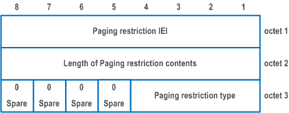
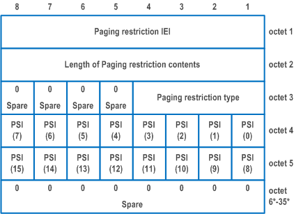
| Paging restriction type (bits 4 to 1 of octet 3) | |
| Bits
4 3 2 1 | |
| 0 0 0 0 | reserved |
| 0 0 0 1 | All paging is restricted |
| 0 0 1 0 | All paging is restricted except for voice service |
| 0 0 1 1 | All paging is restricted except for specified PDU session(s) |
| 0 1 0 0 | All paging is restricted except for voice service and specified PDU session(s) |
| All other values are reserved. Bits 5 to 8 of octet 3 are spare and shall be coded as zero. | |
| PSI(x) (bits 8 to 1 of octet 4 and octet 5): | |
| This field indicates the PDU session identity of the PDU session for which paging is restricted. | |
| PSI(0): (bit 1 of octet 4) | |
| Spare and shall be coded as zero. | |
| PSI(1) - PSI(15): | |
| 0 | indicates that paging is restricted for the PDU session associated with the PDU session identity. |
| 1 | indicates that paging is not restricted for the PDU session associated with the PDU session identity. |
| All bits in octet 6 to 35 are spare and shall be coded as zero, if the respective octet is included in the information element. | |
9.11.3.78 Void
9.11.3.79 NID |R17| p. 974
9.11.3.80 PEIPS assistance information |R17| p. 974
The purpose of the PEIPS assistance information, information element is to transfer the required assistance information to indicate the paging subgroup used when paging the UE.
The coding of the information element allows combining different types of PEIPS assistance information.
The PEIPS assistance information, information element is coded as shown in Figure 9.11.3.80.1, Figure 9.11.3.80.2, Figure 9.11.3.80.3 and Table 9.11.3.80.1.
The PEIPS assistance information is a type 4 information element, with a minimum length of 3 octets.
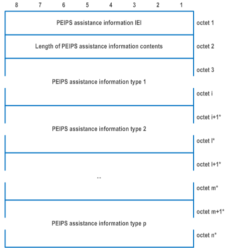


| Value part of the PEIPS assistance information information element (octets 3 to n) The value part of the PEIPS assistance information information element consists of one or several types of PEIPS assistance information. PEIPS assistance information type: | |
| Type of information (octet 1) | |
| Bits
8 7 6 | |
| 0 0 0 | Paging subgroup ID |
| 0 0 1 | UE paging probability information |
| All other values are reserved. | |
| Paging subgroup ID value: (octet 1, bits 1-5) | |
| This field contains the value (in decimal) of paging subgroup ID that is assigned by the AMF for paging the UE. This field has a valid range of values from (0-7). All other values are unused and shall be interpreted as 0 by this version of the protocol. | |
| UE paging probability information value: (octet 1, bits 1-5) | |
| This field contains the value of UE paging probability information provided by the UE to the AMF. It represents the probability of the UE receiving the paging. | |
| Bits
5 4 3 2 1 | UE paging probability information value |
| 0 0 0 0 0 | p00 (UE calculated paging probability is 0%) |
| 0 0 0 0 1 | p05 (UE calculated paging probability > 0% and ≤ 5%) |
| 0 0 0 1 0 | p10 (UE calculated paging probability > 5% and ≤ 10%) |
| 0 0 0 1 1 | p15 (UE calculated paging probability > 10% and ≤ 15%) |
| 0 0 1 0 0 | p20 (UE calculated paging probability > 15% and ≤ 20%) |
| 0 0 1 0 1 | p25 (UE calculated paging probability > 20% and ≤ 25%) |
| 0 0 1 1 0 | p30 (UE calculated paging probability > 25% and ≤ 30%) |
| 0 0 1 1 1 | p35 (UE calculated paging probability > 30% and ≤ 35%) |
| 0 1 0 0 0 | p40 (UE calculated paging probability > 35% and ≤ 40%) |
| 0 1 0 0 1 | p45 (UE calculated paging probability > 40% and ≤ 45%) |
| 0 1 0 1 0 | p50 (UE calculated paging probability > 45% and ≤ 50%) |
| 0 1 0 1 1 | p55 (UE calculated paging probability > 50% and ≤ 55%) |
| 0 1 1 0 0 | p60 (UE calculated paging probability > 55% and ≤ 60%) |
| 0 1 1 0 1 | p65 (UE calculated paging probability > 60% and ≤ 65%) |
| 0 1 1 1 0 | p70 (UE calculated paging probability > 65% and ≤ 70%) |
| 0 1 1 1 1 | p75 (UE calculated paging probability > 70% and ≤ 75%) |
| 1 0 0 0 0 | p80 (UE calculated paging probability > 75% and ≤ 80%) |
| 1 0 0 0 1 | p85 (UE calculated paging probability > 80% and ≤ 85%) |
| 1 0 0 1 0 | p90 (UE calculated paging probability > 85% and ≤ 90%) |
| 1 0 0 1 1 | p95 (UE calculated paging probability > 90% and ≤ 95%) |
| 1 0 1 0 0 | p100 (UE calculated paging probability > 95% and ≤ 100%) |
| All other values shall be interpreted as 10100 by this version of the protocol. | |
9.11.3.81 5GS additional request result |R17| p. 976
The purpose of the 5GS additional request result information element is to inform the UE about the result of additional request.
The 5GS additional request result information element is coded as shown in Figure 9.11.3.81.1 and Table 9.11.3.81.1.
The 5GS additional request result is a type 4 information element with a length of 3 octets.
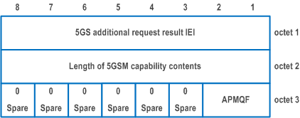
| Paging restriction decision (PRD) (bits 2 to 1 of octet 3) | |
| Bits
2 1 | |
| 0 0 | no additional information |
| 0 1 | paging restriction is accepted |
| 1 0 | paging restriction is rejected |
| All other values are reserved. | |
| Bits 3 to 8 of octet 3 are spare and shall be coded as zero. | |
9.11.3.82 NSSRG information |R17| p. 977
The purpose of the NSSRG information information element is to identify one or more NSSRG values associated with each of the HPLMN S-NSSAIs in a configured NSSAI.
The NSSRG information information element is coded as shown in Figure 9.11.3.82.1, Figure 9.11.3.82.2 and Table 9.11.3.82.1.
The NSSRG information is a type 6 information element with minimum length of 7 octets and maximum length of 4099 octets.
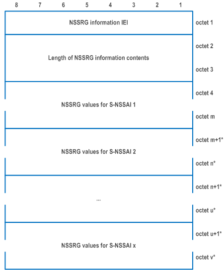
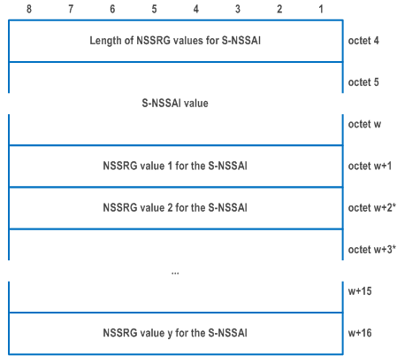
| Value part of the NSSRG information information element (octet 4 to v) | |
| The value part of the NSSRG information information element consists of one or more NSSRG values for each S-NSSAI in the Configured NSSAI IE. | |
| S-NSSAI value (octet 5 to w) (see NOTE 2) | |
| S-NSSAI value is coded as the length and value part of S-NSSAI information element as specified in subclause 9.11.2.8 starting with the second octet. See NOTE 1. | |
| NSSRG value for the S-NSSAI (octet w+1) | |
| This field contains the 8 bit NSSRG value. | |
|
NOTE 1:
If a mapped HPLMN SST is included in a S-NSSAI value, then the NSSRG value(s) are associated with the Mapped HPLMN SST, and the Mapped HPLMN SD, if included.
NOTE 2:
The NSSRG information IE shall contain the complete set of S-NSSAI(s) included in the configured NSSAI.
NOTE 3:
The number of NSSRG values associated with an S-NSSAI cannot exceed 16. If there are more than 16 NSSRG values for an S-NSSAI in the NSSRG information, then the UE shall retain only the first 16 NSSRG values and ignore the rest.
|
|
9.11.3.83 List of PLMNs to be used in disaster condition |R17| p. 978
The purpose of the list of PLMNs to be used in disaster condition information element is to provide the "list of PLMN(s) to be used in disaster condition" associated with the serving PLMN to the UE.
The list of PLMNs to be used in disaster condition information element is coded as shown in Figure 9.11.3.83.1 and Figure 9.11.3.83.2 and Table 9.11.3.83.1.
The list of PLMNs to be used in disaster condition is a type 4 information element, with a minimum length of 2 octets.
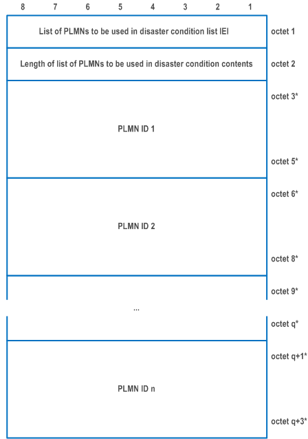
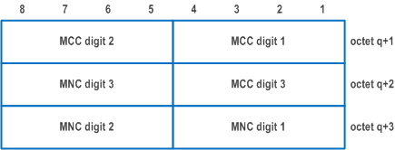
| MCC, Mobile country code (octet q+1 and bits 1 to 4 octet q+2) | |
| The MCC field is coded as in ITU-T Recommendation E.212 [42], Annex A. | |
| MNC, Mobile network code (bits 5 to 8 of octet q+2 and octet q+3) | |
| The coding of this field is the responsibility of each administration but BCD coding shall be used. The MNC shall consist of 2 or 3 digits. If a network operator decides to use only two digits in the MNC, bits 5 to 8 of octet q+2 shall be coded as "1111". | |
| The MCC and MNC digits are coded as octets 6 to 8 of the Temporary mobile group identity IE in Figure 10.5.154 of TS 24.008. | |
|
NOTE:
The PLMN IDs are provided in decreasing order of priority, i.e. PLMN ID 1 indicates highest priority and PLMN ID n indicates lowest priority.
|
|
9.11.3.84 Registration wait range |R17| p. 979
The purpose of the registration wait range information element is to provide the disaster roaming wait range or the disaster return wait range to the UE.
The registration wait range information element is coded as shown in Figure 9.11.3.84.1 and Table 9.11.3.84.1.
The registration wait range is a type 4 information element, with a length of 4 octets.
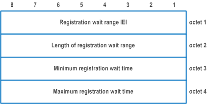
| Minimum registration wait time (octet 3) | |
| The minimum registration wait time contains the minimum duration of the registration wait time, encoded as octet 2 of the GPRS timer information element (see subclause 10.5.7.3 of TS 24.008). | |
| Maximum registration wait time (octet 4) | |
| The maximum registration wait time contains the maximum duration of the registration wait time, encoded as octet 2 of the GPRS timer information element (see subclause 10.5.7.3 of TS 24.008). | |
9.11.3.85 PLMN identity |R17| p. 980
The purpose of the PLMN identity information element is to provide a PLMN identity.
The PLMN identity information element is coded as shown in Figure 9.11.3.85.1, and Table 9.11.3.85.1.
The PLMN identity is a type 4 information element.
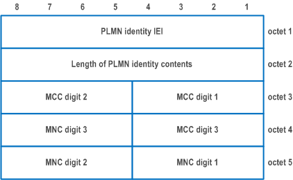
| MCC, Mobile country code (octet 3, octet 4 bits 1 to 4) | |
| The MCC field is coded as in ITU-T Recommendation E.212 [42], Annex A. | |
| MNC, Mobile network code (octet 4 bits 5 to 8, octet 5) | |
| The coding of this field is the responsibility of each administration but BCD coding shall be used. The MNC shall consist of 2 or 3 digits. If a network operator decides to use only two digits in the MNC, bits 5 to 8 of octet 4 shall be coded as "1111". | |
| The MCC and MNC digits are coded as octets 6 to 8 of the Temporary mobile group identity IE in Figure 10.5.154 of TS 24.008. | |
9.11.3.86 Extended CAG information list |R17| p. 980
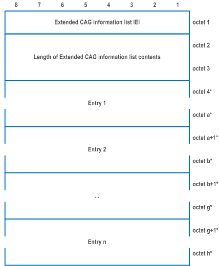
The purpose of the Extended CAG information list information element is to provide "CAG information list" or to delete the "CAG information list" at the UE.
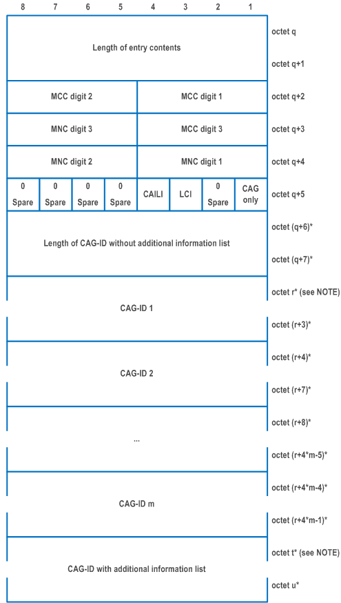
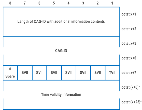
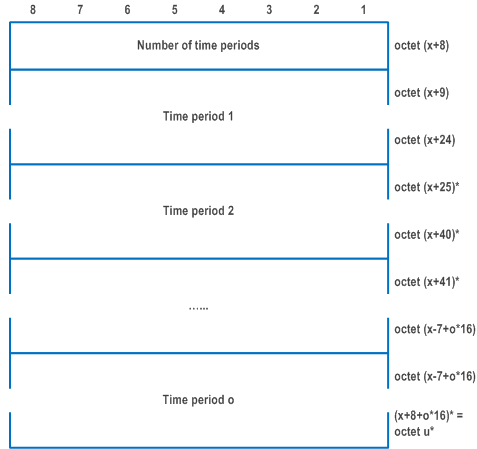
The Extended CAG information list information element is coded as shown in Figure 9.11.3.86.1, Figure 9.11.3.86.2, Figure 9.11.3.86.3, Figure 9.11.3.86.4, Figure 9.11.3.86.5 and Table 9.11.3.86.1.
The Extended CAG information list is a type 6 information element, with a minimum length of 3 octets.
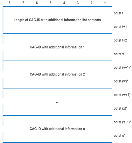
| Value part of the Extended CAG information list information element (octet 4 to h) | |
| The value part of the Extended CAG information list information element consists of one or more entries. | |
| Entry n: | |
| Length of entry contents (octet q and q+1) | |
| MCC, Mobile country code (octet q+2 and bits 1 to 4 octet q+3) | |
| The MCC field is coded as in ITU-T Recommendation E.212 [42], Annex A. | |
| MNC, Mobile network code (bits 5 to 8 of octet q+3 and octet q+4) | |
| The coding of this field is the responsibility of each administration, but BCD coding shall be used. The MNC shall consist of 2 or 3 digits. If a network operator decides to use only two digits in the MNC, bits 5 to 8 of octet q+2 shall be coded as "1111". | |
| The MCC and MNC digits are coded as octets 6 to 8 of the Temporary mobile group identity IE in Figure 10.5.154 of TS 24.008. | |
| Indication that the UE is only allowed to access 5GS via CAG cells (CAGonly) (bit 1 of octet q+5) | |
| 0 | "Indication that the UE is only allowed to access 5GS via CAG cells" is not set (i.e., the UE is allowed to access 5GS via non-CAG cells) |
| 1 | "Indication that the UE is only allowed to access 5GS via CAG cells" is set (i.e., the UE is not allowed to access 5GS via non-CAG cells) |
| Length of CAG-IDs indicator (LCI) (bit 3 of octet q+5) | |
| 0 | Length of CAG-IDs field is absent |
| 1 | Length of CAG-IDs field is present |
| If the UE does not support enhanced CAG information, the LCI bit shall be set to "Length of CAG-IDs field is absent". | |
| CAG-ID with additional information list indicator (CAILI) (bit 4 of octet q+5) | |
| 0 | CAG-ID with additional information list field is absent |
| 1 | CAG-ID with additional information list field is present |
| If the UE does not support enhanced CAG information, the CAILI bit shall be set to "CAG-ID with additional information list field is absent". | |
| Length of CAG-ID without additional information list (octet q+6 to octet q+7) | |
| This field indicates length of CAG-ID fields in octet r to octet (r+4*m-1). | |
| CAG-ID m (octet r+4*m-4 to octet r+4*m-1) | |
| This field contains the 32 bit CAG-ID which is not associated with additional information. The coding of the CAG-ID is defined as the CAG-Identifier in TS 23.003. See NOTE 4. | |
| If the length of entry contents field indicates a length bigger than indicated in Figure 9.11.3.86.1, receiving entity shall ignore any superfluous octets located at the end of the entry contents. | |
| CAG-ID (octet x+3 to octet x+6) | |
| This field contains the 32 bit CAG-ID which is associated with additional information. The additional information is indicated in remaining fields of Figure 9.11.3.86.4. The coding of the CAG-ID is defined as the CAG-Identifier in TS 23.003. | |
| Time validity information indicator (TVII) (bit 1 of octet x+7) | |
| 0 | Time validity information field is absent |
| 1 | Time validity information field is present |
| Spare validity information indicator (SVII) | |
| 0 | Spare validity information is absent |
| 1 | Spare validity information is present |
| The SVII bit indicates presence of a validity information not specified in the present version of the present document. See NOTE 5. | |
| If the SVII bit is set to "Spare validity information is present", the receiving entity shall ignore the CAG-ID with additional information field. | |
| Time period (octet x+25 to octet x+40) | |
| The time period information field is coded as the route selection descriptor component value field for "time window type" specified in TS 24.526 Table 5.2.1. | |
| If the length of CAG-ID with additional information contents field indicates a length bigger than indicated in Figure 9.11.3.86.4, receiving entity shall ignore any superfluous octets located at the end of the CAG-ID with additional information contents. | |
|
NOTE 1:
The length of extended CAG information list contents field shall be 0 if no subscription data for CAG information list exists.
NOTE 2:
The length of entry contents field shall be 4 if there is no allowed CAG-ID for the PLMN.
NOTE 3:
For a given PLMN ID, there shall be up to one entry field containing the MCC value and the MNC value of the PLMN ID.
NOTE 4:
CAG-ID field containing a CAG-ID which is not associated with additional information, can be provided regardless whether the LCI bit is set to "Length of CAG-IDs field is absent" or "Length of CAG-IDs field is present".
NOTE 5:
In a future version of the present document, semantic of this bit can be changed to indicate presence or absence of an additional validity information.
|
|
9.11.3.87 NSAG information |R17| p. 985
The purpose of the NSAG information information element is to provide the NSAG information to the UE.
The NSAG information information element is coded as shown in Figure 9.11.3.87.1, Figure 9.11.3.87.2 and Figure 9.11.3.87.3, and Table 9.11.3.87.1.
The NSAG information information element can contain a maximum of 32 NSAG entries.
In the NSAG information information element, at most 4 NSAG entries can contain a TAI list.
The NSAG information is a type 6 information element, with a minimum length of 9 octets and a maximum length of 3143 octets.
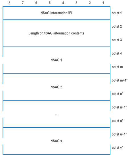
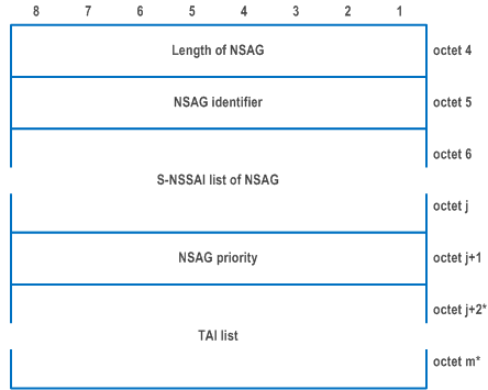
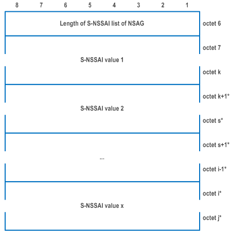
| NSAG part of the NSAG information information element (octet 4 to m) | |
| Each entry of the NSAG information information element consists of one NSAG in the NSAG information IE. | |
| NSAG identifier(octet 5) | |
| NSAG identifier field contains an 8 bits NSAG ID value. | |
| S-NSSAI list of NSAG (octet 6 to j) | |
| S-NSSAI list of NSAG field consists of one or more S-NSSAIs in the configured NSSAI. Each S-NSSAI in S-NSSAI list of NSAG field is coded as the length and value part of S-NSSAI information element as specified in subclause 9.11.2.8 starting with the second octet, without the mapped HPLMN SST field and without the mapped HPLMN SD field. | |
| NSAG priority (octet j+1) | |
| The NSAG priority field represents the binary coded value of NSAG priority for cell reselection (see TS 38.304) and random access (see TS 38.321). The range of the NSAG priority is 0 to 255. A lower value indicates a higher priority, with 0 as the highest priority. | |
| TAI list (octet j+2 to m) | |
| The TAI list field is coded as the length and value part of the 5GS tracking area identity list IE defined in subclause 9.11.3.9 starting with the second octet. | |
9.11.3.88 ProSe relay transaction identity |R17| p. 986
The purpose of the ProSe relay transaction identity (PRTI) information element is to uniquely identify an authentication and key agreement procedure for 5G ProSe UE-to-network relay or 5G ProSe UE-to-UE relay. The PRTI allows distinguishing up to 254 different bi-directional messages.
The ProSe relay transaction identity information element is coded as shown in Figure 9.11.3.88.1 and Table 9.11.3.88.1.
The ProSe relay transaction identity is a type 3 information element with a length of 2 octets.

| ProSe relay transaction identity value (octet 2) | |
|
Bits
8 7 6 5 4 3 2 1 | |
| 0 0 0 0 0 0 0 0 | No ProSe relay transaction identity assigned |
| 0 0 0 0 0 0 0 1 | |
| to | ProSe relay transaction identity value |
| 1 1 1 1 1 1 1 0 | |
| 1 1 1 1 1 1 1 1 | Reserved |
9.11.3.89 Relay key request parameters |R17| p. 987
The purpose of the relay key request parameters information element is to transport the parameters of the key request for 5G ProSe UE-to-network relay or 5G ProSe UE-to-UE relay as specified in TS 33.503.
The relay key request parameters information element is coded as shown in Figure 9.11.3.89.1, Figure 9.11.3.89.2 and Table 9.11.3.89.1.
The relay key request parameters is a type 6 information element.
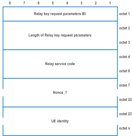
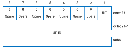
| Relay service code (octet 4 to 6) | |
| The relay service code contains 24-bit relay service code as defined in TS 24.554. | |
| Nonce_1 (octet 7 to 22) | |
| Nonce_1 is the 128-bit nonce value as defined in TS 24.554. | |
| UE ID type (UIT) (octet 23, bit 1) | |
| Bit
1 | |
| 0 | SUCI |
| 1 | CP-PRUK ID |
| UE ID (octet 23+1 to n) | |
| UE ID indicates the value of the 5G ProSe remote UE identity or the 5G ProSe end UE identity. If the UE ID type is set to SUCI, the UE ID is coded as 5GS mobile identity IE starting from octet 2 with the Type of identity set to "SUCI" (see subclause 9.11.3.4). If the UE ID type is set to CP-PRUK ID, the UE ID is coded as the CP-PRUK ID as defined in TS 33.503. | |
9.11.3.90 Relay key response parameters |R17| p. 988
The purpose of the relay key response parameters information element is to transport the parameters of the key response for 5G ProSe UE-to-network relay or 5G ProSe UE-to-UE relay as specified in TS 33.503.
The relay key response parameters information element is coded as shown in Figure 9.11.3.90.1 and Table 9.11.3.90.1.
The relay key response parameters is a type 6 information element.
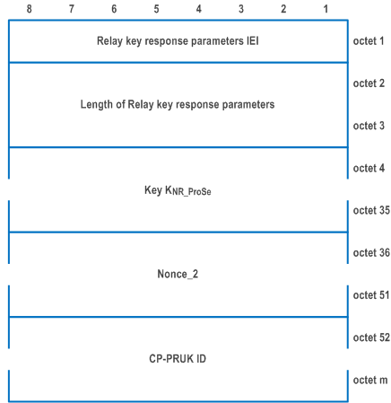
| Key KNR_ProSe (octet 5 to 35) | |
| Key KNR_ProSe contains a 256-bit root key that is established between the two entities that communicating using NR PC5 unicast link as defined in TS 33.503. | |
| Nonce_2 (octet 36 to 51) | |
| Nonce_2 is the 128-bit nonce value as defined in TS 24.554. | |
| CP-PRUK ID (octet 52 to m) | |
| The CP-PRUK ID is defined in TS 33.503. | |
9.11.3.91 Priority indicator |R17| p. 989
The purpose of the Priority indicator information element is to convey a priority indication to the UE.
The Priority indicator information element is coded as shown in Figure 9.11.3.91.1 and Table 9.11.3.91.1.
The Priority indicator is a type 1 information element.

| MPS indicator (MPSI) (octet 1, bit 1) | |
| 0 | Access identity 1 not valid |
| 1 | Access identity 1 valid |
| MCS indicator (MCSI) (octet 1, bit 2) | |
| 0 | Access identity 2 not valid |
| 1 | Access identity 2 valid |
| Bits 3, 4 are spare and shall be coded as zero. | |
9.11.3.92 SNPN list |R18| p. 989
The purpose of the SNPN list information element is to provide a list of SNPN identities.
The SNPN list information element is coded as shown in Figure 9.11.3.92.1, Table 9.11.3.92.1, Figure 9.11.3.92.2 and Table 9.11.3.92.2.
The SNPN list is a type 4 information element with a minimum length of 11 octets and a maximum length of 137 octets.
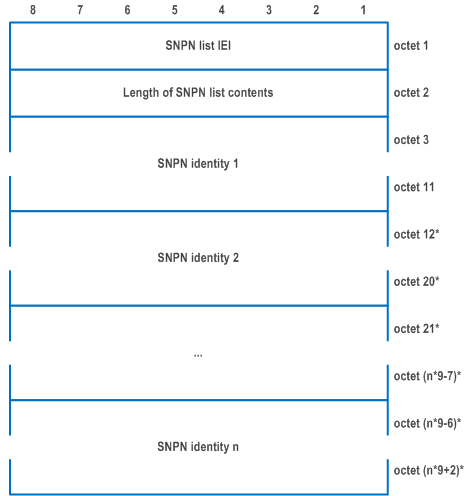
| Each SNPN identity field is coded according to Figure 9.11.3.92.2 and Table 9.11.3.92.2. | |
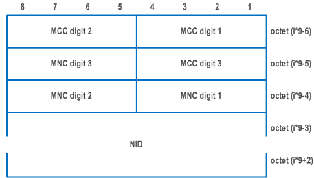
| MCC, Mobile country code (octet (i*9-6), octet (i*9-5) bits 1 to 4) | |
| The MCC field is coded as in ITU-T Recommendation E.212 [42], Annex A. | |
| MNC, Mobile network code (octet (i*9-5) bits 5 to 8, octet (i*9-4)) | |
| The coding of this field is the responsibility of each administration but BCD coding shall be used. The MNC shall consist of 2 or 3 digits. If a network operator decides to use only two digits in the MNC, bits 5 to 8 of octet 6 shall be coded as "1111" | |
| The MCC and MNC digits are coded as octets 6 to 8 of the Temporary mobile group identity IE in Figure 10.5.154 of TS 24.008. | |
| NID (octet (i*9-3) to octet (i*9+2)) | |
| NID field is coded as the NID field of NID IE as specified in Figure 9.2.7-2 and Table 9.2.7-2 of TS 24.502 starting with the octet 3 and ending with the octet 8. | |
9.11.3.93 N3IWF identifier |R18| p. 990
The purpose of the N3IWF identifier information element is to enable the network to assign the UE, a suitable N3IWF for the requested NSSAI.
The N3IWF identifier information element is coded as shown in Figure 9.11.3.93.1, Figure 9.11.3.93.2, Figure 9.11.3.93.3 and Table 9.11.3.93.1.
The N3IWF identifier information element is a type 4 information element with a minimum length of 7 octets.
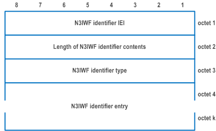


| N3IWF identifier type (octet 1) is set as follows: | |
|
Bits
8 7 6 5 4 3 2 1 | |
| 0 0 0 0 0 0 0 0 | IPv4 |
| 0 0 0 0 0 0 1 0 | IPv6 |
| 0 0 0 0 0 0 1 1 | IPv4v6 |
| 0 0 0 0 0 1 0 0 | FQDN |
| All other values are reserved. | |
| If the N3IWF identifier type indicates IPv4, then the N3IWF IP address field contains an IPv4 address in octet 4 to octet 7. | |
| If the N3IWF identifier type indicates IPv6, then the N3IWF IP address field contains an IPv6 address in octet 4 to octet 19. | |
| If the N3IWF identifier type indicates IPv4v6, then the N3IWF IP address field contains two IP addresses. The first IP address is an IPv4 address in octet 4 to octet 7. The second IP address is an IPv6 address in octet 8 to octet 23. | |
| If the N3IWF identifier type indicates FQDN, the N3IWF FQDN field in octet 4 to octet n is encoded as defined in subclauses 28.3.2.2.2, 28.3.2.2.3, 28.3.2.2.8 or 28.3.2.2.9 in TS 23.003. | |
9.11.3.94 TNAN information |R18| p. 991
The purpose of the TNAN information information element is to enable the network to assign the UE, a suitable TNAN information (SSID and TNGF ID) for the requested NSSAI.
The TNAN information information element is coded as shown in Figure 9.11.3.94.1 and Table 9.11.3.94.1.
The TNAN information information element is a type 4 information element with a minimum length of 3 octets.
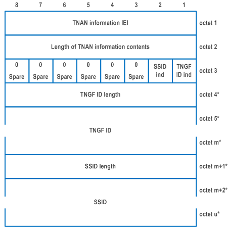
| TNGF ID indication (TNGF ID ind) (bit 1 of octet 3) | |
| The TNGF ID ind indicates whether the TNGF ID length field and the TNGF ID field are included in the TNAN information or not. | |
| 0 | TNGF ID length and TNGF ID not included |
| 1 | TNGF ID length and TNGF ID included |
| SSID indication (SSID ind) (bit 2 of octet 3) | |
| The SSID ind indicates whether the SSID length field and the SSID field are included in the TNAN information or not. | |
| 0 | SSID length and SSID not included |
| 1 | SSID length and SSID included |
| Bits 3 to 8 of octet 3 are spare and shall be coded as zero | |
| TNGF ID length (octet 4) indicates the length of the TNGF ID field. | |
| TNGF ID (octets 5 to m) | |
| The TNGF ID field is an octet string that indicates the TNGF ID. | |
| SSID length (octet m+1) indicates the length of the SSID field. | |
| SSID (octets m+2 to u) | |
| The SSID field is an octet string which shall have a maximum length of 32 octets (see IEEE Std 802.11 [59]). | |
9.11.3.95 RAN timing synchronization |R18| p. 992
The purpose of the RAN timing synchronization IE is to provide information related to the RAN timing synchronization.
The RAN timing synchronization information element is coded as shown in Figure 9.11.3.95.1 and Table 9.11.3.95.1.
The RAN timing synchronization is a type 4 information element with a length of 3 octets.
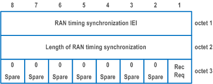
| Request to reconnect to the network upon receiving an indication of a change in the RAN timing synchronization status (RecReq) (octet 3, bit 1) | |
| 0 | Reconnection not requested |
| 1 | Reconnection requested |
| Bits 2 to 8 of octet 3 are spare and shall be coded as zero. | |
9.11.3.96 Extended LADN information |R18| p. 993
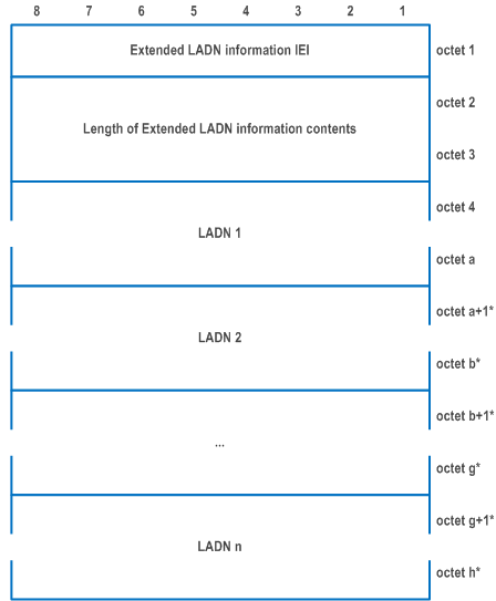
The purpose of the Extended LADN information information element is to provide the UE with the LADN service area for each available LADN associated for an LADN DNN and an S-NSSAI in the current registration area or to delete the Extended LADN information at the UE.
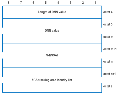
The Extended LADN information information element is coded as shown in Figure 9.11.3.96.1, Figure 9.11.3.96.2 and Table 9.11.3.96.1.
The Extended LADN information is a type 6 information element with a minimum length of 3 octets and a maximum length of 1787 octets.
The Extended LADN information information element can contain a minimum of 0 and a maximum of 8 different LADNs each including a DNN, an S-NSSAI and a 5GS tracking area identity list.
| Value part of the Extended LADN information information element (octet 4 to octet h) | |
| The value part of the Extended LADN information information element consists of one or several LADNs. Each LADN (e.g. octet 4 to octet a) consists of one DNN value, one S-NSSAI and one 5GS tracking area identity list. The length of each LADN is determined by the length of DNN value field, the length of S-NSSAI field and the length of 5GS tracking area identity list field. | |
| The UE shall store the complete list as received. If more than 8 LADNs are included in this information element, the UE shall store the first 8 LADNs and ignore the remaining octets of the information element. | |
| DNN value (octet 5 to octet m): | |
| DNN value field is coded as DNN value part of DNN information element as specified in subclause 9.11.2.1B starting with the third octet. | |
| S-NSSAI (octet m+1 to n) (see NOTE 1) | |
| S-NSSAI is coded as the length and value part of S-NSSAI information element as specified in subclause 9.11.2.8 starting with the second octet. | |
| 5GS tracking area identity list (octet m+1 to octet a): | |
| 5GS tracking area identity list field is coded as the length and the value part of the 5GS Tracking area identity list information element as specified in subclause 9.11.3.9 starting with the second octet. | |
|
NOTE 1:
The S-NSSAI included in the Extended LADN information information element shall be an S-NSSAI from, an allowed NSSAI or an partially allowed NSSAI provided to the UE.
|
|
9.11.3.97 Alternative NSSAI |R18| p. 994
The purpose of the Alternative NSSAI information element is to identify a list of mapping information between the S-NSSAI to be replaced and the alternative S-NSSAI.
The Alternative NSSAI information element is coded as shown in Figure 9.11.3.97.1, Figure 9.11.3.97.2 and Table 9.11.3.97.1.
The Alternative NSSAI is a type 4 information element with minimum length of 2 octets and maximum length of 146 octets.
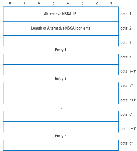
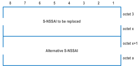
| Value part of the Alternative NSSAI information element (octet 3 to d) | |
| The value part of the Alternative NSSAI information element consists of one or more entries, each entry consists of one S-NSSAI to be replaced and one alternative S-NSSAI. The number of entries shall not exceed eight. | |
| S-NSSAI to be replaced (octet 3 to x) (see NOTE) | |
| S-NSSAI to be replaced is coded as the length and value part of S-NSSAI information element as specified in subclause 9.11.2.8 starting with the second octet. | |
| Alternative S-NSSAI (octet x+1 to a) | |
| Alternative S-NSSAI is coded as the length and value part of S-NSSAI information element as specified in subclause 9.11.2.8 starting with the second octet. | |
|
NOTE:
The S-NSSAI to be replaced shall be one S-NSSAI included in the allowed NSSAI.
|
|
9.11.3.98 Type 6 IE container |R18| p. 995
The purpose of the Type 6 IE container information element is to transfer type 6 IEs of format TLV-E explicitly specified for inclusion in this information element for the respective message.
The rules for the IEI value encoding specified in clause 11.2.4 of TS 24.007, are not applicable for the IEIs of the type 6 IEs within the Type 6 IE container information element. These IEIs can take any value in the range 00 to FF (hexadecimal).
The type 6 IE container information element is coded as shown in Figure 9.11.3.98.1, Figure 9.11.3.98.2 and Table 9.11.3.98.1.
The type 6 IE container is a type 6 information element with a minimum length of 6 octets.
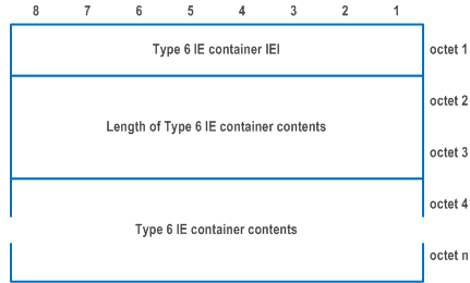
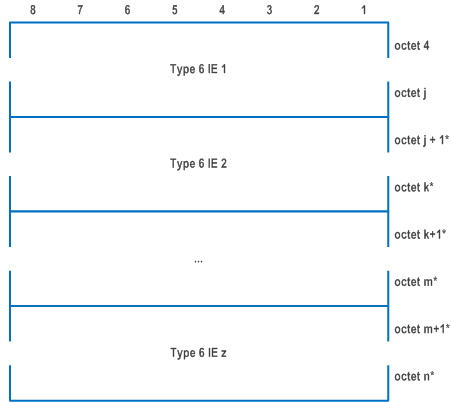
| Type 6 IE container contents (octets 4 to n) | |
| The Type 6 IE container is coded according to Figure 9.11.3.98.2. | |
| The sender of this information element shall encode each type 6 IE included in the contents in format TLV-E. | |
| For the coding of each of the type 6 IEs in the type 6 IE container, see the definition of the respective type 6 IE in subclause 9.11 | |
9.11.3.99 Non-3GPP access path switching indication |R18| p. 996
The purpose of the Non-3GPP access path switching indication information element is to indicate whether the UE supports the non-3GPP access path switching for the PDU session.
The Non-3GPP access path switching indication information element is coded as shown in Figure 9.11.3.99.1 and Table 9.11.3.99.1.
The Non-3GPP access path switching indication is a type 4 information element with a length of 3 octets.
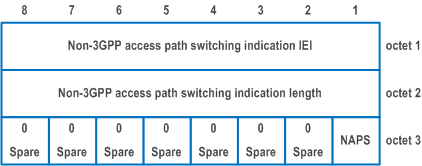
| Non-3GPP access path switching (NAPS) (octet 3, bit 1) | |
| This bit indicates whether non-3GPP access path switching is supported. | |
| 0 | non-3GPP access path switching not supported |
| 1 | non-3GPP access path switching supported |
| Bits 2 to 8 of octet 3 are spare and shall be coded as zero. | |
9.11.3.100 S-NSSAI location validity information |R18| p. 997
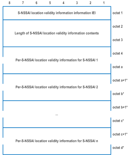
The purpose of the S-NSSAI location validity information information element is to provide the S-NSSAI location validity information to the UE.
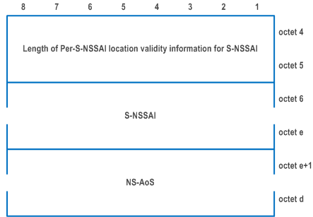
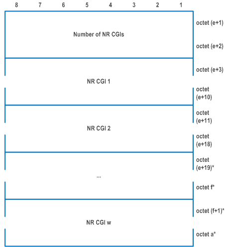
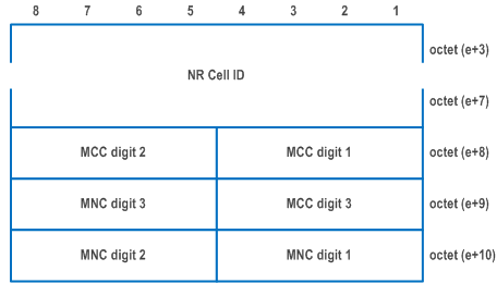
The S-NSSAI location validity information information element is coded as shown in Figure 9.11.3.100.1, Figure 9.11.3.100.2, Figure 9.11.3.100.3 and Figure 9.11.3.100.4 and Table 9.11.3.100.1.
The S-NSSAI location validity information information element can contain per-S-NSSAI location validity information for maximum 16 S-NSSAIs.
The S-NSSAI location validity information information is a type 6 information element with a minimum length of 17 octets and a maximum length of 38611 octets.
| S-NSSAI (octet 6 to e) | |
| S-NSSAI value is coded as the length and value part of S-NSSAI information element as specified in subclause 9.11.2.8 starting with the second octet. | |
| NS-AoS (octet e+1 to octet a) | |
| NS-AoS filed consists of the Number of NR cell IDs field and at least two NR CGIs. | |
| Number of NR CGIs (octet e+1 to octet e+2) | |
| The field indicates the number of NR CGIs included in octets e+3 to octet a. (NOTE). | |
| NR CGI (octet e+3 to e+10) | |
| The NR CGI globally identifies an NR cell. It contains the NR Cell ID and the PLMN ID of that cell. | |
| NR Cell ID (octet e+3 to e+7) | |
| The NR Cell ID consists of 36 bits identifying an NR Cell ID as specified in subclause 9.3.1.7 of TS 38.413, in hexadecimal representation. Bit 8 of octet e+3 is the most significant bit and bit 5 of octet e+7 is the least significant bit. Bits 1 to 4 of octet e+7 are spare and shall be coded as zero. | |
| MCC, Mobile country code (octet e+8 and bits 1 to 4 octet e+9) | |
| The MCC field is coded as in ITU-T Recommendation E.212 [42], Annex A. | |
| MNC, Mobile network code (bits 5 to 8 of octet e+9 and octet e+10) | |
| The coding of this field is the responsibility of each administration but BCD coding shall be used. The MNC shall consist of 2 or 3 digits. If a network operator decides to use only two digits in the MNC, bits 5 to 8 of octet e+9 shall be coded as "1111". The MCC and MNC digits are coded as octets 6 to 8 of the Temporary mobile group identity IE in Figure 10.5.154 of TS 24.008. | |
9.11.3.101 S-NSSAI time validity information |R18| p. 998
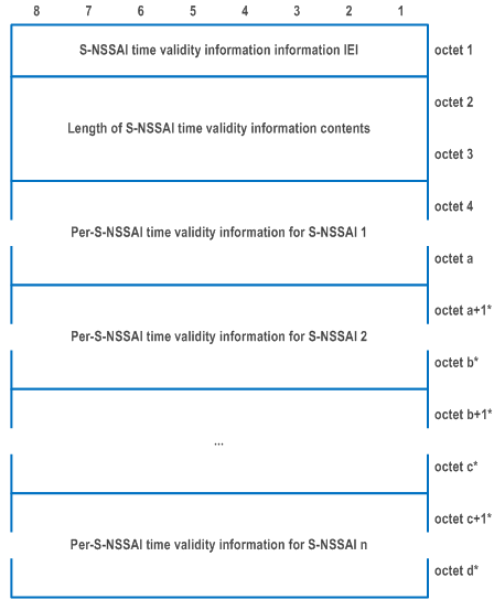
The purpose of the S-NSSAI time validity information information element is to provide S-NSSAI time validity information of one or more S-NSSAIs to the UE.
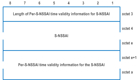
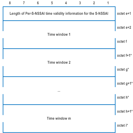
The S-NSSAI time validity information information element is coded as shown in Figure 9.11.3.101.1 and Figure 9.11.3.101.2 and Table 9.11.3.101.1.
The S-NSSAI time validity information information element can contain per-S-NSSAI time validity information for maximum 16 S-NSSAIs.
The S-NSSAI time validity information information is a type 4 information element with a minimum length of 23 octets and a maximum length of 257 octets.
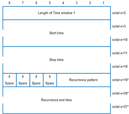
| S-NSSAI (octet 6 to octet e) | |
| S-NSSAI value is coded as the length and value part of S-NSSAI information element as specified in subclause 9.11.2.8 starting with the second octet. | |
| Start time (octet e+3 to octet e+10) | |
| The field indicates the time when the network slice identified by the S-NSSAI becomes available (for the first time if octet e+20 is included) and is represented by the number of seconds since 00:00:00 on 1 January 1970 UTC and is encoded as the 64-bit NTP timestamp format defined in IETF RFC 5905, where binary encoding of the integer part is in the first 32 bits and binary encoding of the fraction part in the last 32 bits. | |
| Stop time (octet e+11 to octet e+18) | |
| The field indicates the time when the network slice identified by the S-NSSAI becomes unavailable (for the first time if octet e+20 is included) and is represented by the number of seconds since 00:00:00 on 1 January 1970 UTC and is encoded as the 64-bit NTP timestamp format defined in IETF RFC 5905, where binary encoding of the integer part is in the first 32 bits and binary encoding of the fraction part in the last 32 bits. | |
| Recurrence pattern (bit 1 to bit 4 of octet e+19) | |
| Bits
4 3 2 1 | |
| 0 0 0 0 | Everyday |
| 0 0 0 1 | Every weekday |
| 0 0 1 0 | Every week |
| 0 0 1 1 | Every 2 weeks |
| 0 1 0 0 | Every month (absolute) |
| 0 1 0 1 | Every month (relative) |
| 0 1 1 0 | Every quarter (absolute) |
| 0 1 1 1 | Every quarter (relative) |
| 1 0 0 0 | Every 6 months (absolute) |
| 1 0 0 1 | Every 6 months (relative) |
| All other values are reserved. | |
The recurrence pattern indicates how often the time window is repeated. For example, if the time window starts at 13:00 on Wednesday January 1st 2020 and stops at 13:30 on Wednesday January 1st 2020 and the recurrent pattern is set to:
| |
| Recurrence end time (octet e+20 to octet e+27) | |
| The field indicates the time when the repetition of the time window ends. If the field is not included and octet e+19 is included in the IE, the time window is repeated indefinitely. The field is represented by the number of seconds since 00:00:00 on 1 January 1970 UTC and is encoded as the 64-bit NTP timestamp format defined in IETF RFC 5905, where binary encoding of the integer part is in the first 32 bits and binary encoding of the fraction part in the last 32 bits. | |
9.11.3.102 Non-3GPP path switching information |R18| p. 1000
The purpose of the Non-3GPP path switching information information element is to request from the network to keep using the user plane resources of the old non-3GPP access during path switching to the new non-3GPP access.
The Non-3GPP path switching information information element is coded as shown in Figure 9.11.3.102.1 and Table 9.11.3.102.1.
The Non-3GPP path switching information is a type 4 information element with a length of 3 octets.
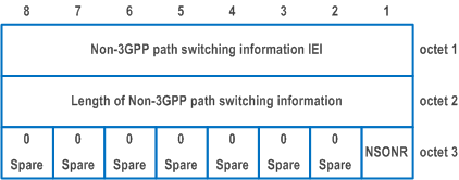
| Non-3GPP path switching while using old non-3GPP resources (NSONR) (octet 3, bit 1) | |
| 0 | non-3GPP path switching while using old non-3GPP resources not requested |
| 1 | non-3GPP path switching while using old non-3GPP resources requested |
| Bits 8 to 2 of octet 3 are spare and shall be coded as zero. | |
9.11.3.103 Partial NSSAI |R18| p. 1001
The purpose of the Partial NSSAI information element is to deliver one or more S-NSSAIs in a set of tracking areas of a registration area from the network to the UE.
The Partial NSSAI information element is coded as shown in Figure 9.11.3.103.1, and Table 9.11.3.103.1.
The Partial NSSAI information element is a type 6 information element, with a minimum length of 3 octets and a maximum length of 808 octets.
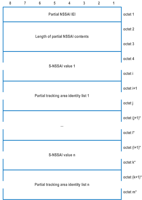
| S-NSSAI value (octet 4 to i) (NOTE 1) | |
| S-NSSAI value is coded as the length and value part of S-NSSAI information element as specified in subclause 9.11.2.8 starting with the second octet. | |
| Partial tracking area identity list (octet i+1 to j) | |
| The partial tracking area identity list field is coded as the length and value part of the 5GS tracking area identity list IE defined in subclause 9.11.3.9 starting with the second octet (NOTE 2). | |
|
NOTE 1:
The maximum number of S-NSSAIs included in this information element is 7.
NOTE 2:
A registration area contains maximum 16 different tracking areas, therefore the partial tracking area identity list can contain at the most 15 tracking area identities.
NOTE 3:
The AMF shall set the Length of partial NSSAI contents to 0 if there are no S-NSSAIs to deliver in a set of tracking areas of a registration area and, the UE shall delete any existing stored partially allowed NSSAI for the current registration area or partially rejected NSSAI for the current registration area.
|
|
9.11.3.104 AUN3 indication |R18| p. 1002
The purpose of the AUN3 indication information element is to indicate to the network that the registration request by the 5G-RG is on behalf of an AUN3 device.
The AUN3 indication information element is coded as shown in Figure 9.11.3.104.1 and Table 9.11.3.104.1.
The AUN3 indication is a type 4 information element with a length of 3 octets.

| AUN3 device indication bit (AUN3REG) (octet 3, bit 1) | |
| 0 | AUN3 device registration is not requested |
| 1 | AUN3 device registration is requested |
| Bits 8 to 2 of octet 3 are spare and shall be coded as zero. | |
9.11.3.105 Feature authorization indication |R18| p. 1002
The purpose of the Feature authorization indication information element is to indicate whether the UE that is authorized to operate certain feature.
The Feature authorization indication is a type 4 information element with a minimum length of 3 octets and maximum length of 257 octets.
The Feature authorization indication information element is coded as shown in Figure 9.11.3.105.1 and Table 9.11.3.105.1.
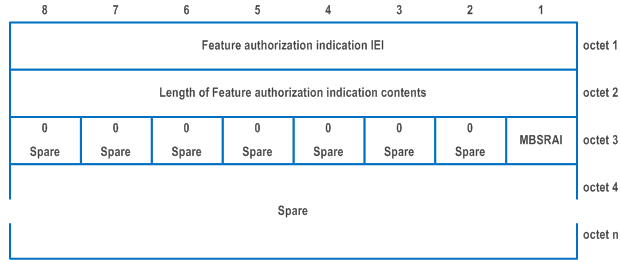
| MBSR authorization indication (MBSRAI) (octet 3, bit 1 to bit 2) | |
| This field indicates whether UE is authorized or not to operate as an MBSR node | |
| Bits
2 1 | |
| 0 0 | no information |
| 0 1 | not authorized to operate as MBSR but allowed to operate as a UE |
| 1 0 | authorized to operate as MBSR |
| 1 1 | spare |
| Bits 3 to 8 of octet 3 are spare and shall be coded as zero. | |
9.11.3.106 Payload container information |R18| p. 1003
The purpose of the Payload container information information element is to provide information related to a payload container.
The Payload container information is a type 1 information element.
The Payload container information information element is coded as shown in Figure 9.11.3.106.1 and Table 9.11.3.106.1.

| PRU related content (PRU) (octet 1, bit 1) | |
| 0 | Payload container not related to PRU |
| 1 | Payload container related to PRU |
| Bits 2 to 4 are spare and shall be coded as zero. | |
9.11.3.107 AUN3 device security key |R18| p. 1003
The purpose of the AUN3 device security key information element is to provide the security keys to the 5G-RG that is acting on behalf of an AUN3 device.
The AUN3 device security key information element is coded as shown in Figure 9.11.3.107.1 and Table 9.11.3.107.1.
The AUN3 device security key is a type 4 information element with a minimum length of 36 octets.
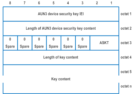
| AUN3 device security key type (ASKT) (bits 1 and 2 of octet 3): | |
| The ASKT indicates which AUN3 device security key is included in the IE. | |
| Bits
2 1 | |
| 0 0 | Master session key is included |
| 0 1 | KWAGF key is included |
| All other values are unused and shall be interpreted as "Master session key is included", if received by the UE. | |
| Key content (octets 5 to n) | |
| If ASKT is set to "Master session key included", the Key content contains the value of the Master session key as defined in TS 33.501. If ASKT is set to "KWAGF key included", the Key content contains the value of the KWAGF key as defined in TS 33.501. | |
9.11.3.108 On-demand NSSAI |R18| p. 1004
The purpose of the On-demand NSSAI information element is to provide a list of one or more on-demand S-NSSAIs and the associated slice deregistration inactivity timer value per the on-demand S-NSSAI to the UE.
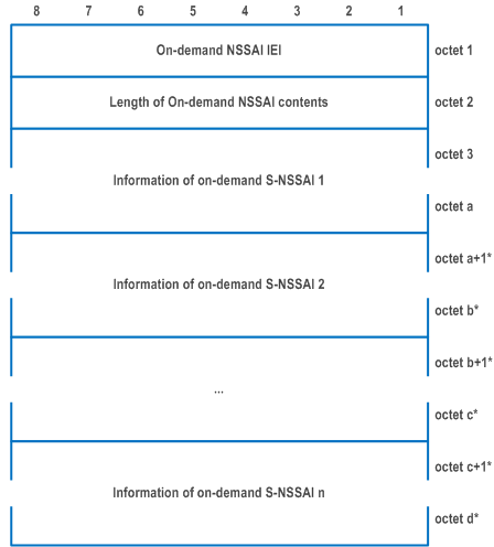
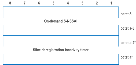
The On-demand NSSAI information element is coded as shown in Figure 9.11.3.108.1, Figure 9.11.3.108.2, and Table 9.11.3.108.1.
The On-demand NSSAI is a type 4 information element with a minimum length of 5 octets and a maximum length of 210 octets.
| Value part of the On-demand NSSAI information element (octet 3 to d) | |
| The value part of the On-demand NSSAI information element consists of one or more Information of on-demand S-NSSAIs. Each Information of on-demand S-NSSAI consists of one on-demand S-NSSAI and optionally the slice deregistration inactivity timer of the on-demand S-NSSAI. The number of information of on-demand S-NSSAIs shall not exceed 16. | |
| On-demand S-NSSAI (octet 4 to a-3) | |
| On-demand S-NSSAI is coded as the length and value part of S-NSSAI information element as specified in subclause 9.11.2.8 starting with the second octet. | |
| Slice deregistration inactivity timer (octet (a-2)* to a*) | |
| Slice deregistration inactivity timer is coded as the value part of Time duration information element as specified in subclause 9.9.3.68 of TS 24.301 starting with the third octet. | |
9.11.3.109 Extended 5GMM cause |R18| p. 1005
The purpose of the Extended 5GMM cause information element is to indicate additional information associated with a 5GMM cause.
The Extended 5GMM cause information element is coded as shown in Figure 9.11.3.109.1 and Table 9.11.3.109.1.
The Extended 5GMM cause is a type 4 information element with a length of 3 octets.

| Sat-NR value (octet 3, bit 1) | |
| 0 | Satellite NG-RAN allowed in PLMN |
| 1 | Satellite NG-RAN not allowed in PLMN |
| Bit 2 to 8 of octet 3 are spare and shall be coded as zero. | |