Content for TS 24.501 Word version: 19.0.0
1…
3…
4…
4.4…
4.4.3…
4.5…
4.5.3…
4.6…
4.7…
4.9…
4.15…
5…
5.2…
5.3…
5.3.2…
5.3.7…
5.3.19…
5.4…
5.4.1.3…
5.4.2…
5.4.4…
5.4.5…
5.4.6…
5.5…
5.5.1.2.4
5.5.1.2.5…
5.5.1.3…
5.5.1.3.4
5.5.1.3.5…
5.5.2…
5.6…
5.6.2…
6…
6.1.4…
6.2…
6.3…
6.3.2…
6.3.3…
6.4…
6.4.1.4…
6.4.2…
6.5…
7…
8…
8.2.9…
8.3…
9…
9.11.2…
9.11.2.10…
9.11.3…
9.11.3.4…
9.11.3.8…
9.11.3.14…
9.11.3.18C…
9.11.3.29…
9.11.3.33…
9.11.3.39…
9.11.3.45…
9.11.3.50…
9.11.3.53A…
9.11.3.68…
9.11.3.75…
9.11.4…
9.11.4.10…
9.11.4.13…
9.11.4.16…
9.11.4.30…
9.12
10…
A…
B…
C…
D…
D.6…
D.6.3…
D.6.8
D.7…
9.11.3.33 NAS message container
9.11.3.34 NAS security algorithms
9.11.3.35 Network name
9.11.3.36 Network slicing indication
9.11.3.36A Non-3GPP NW provided policies
9.11.3.37 NSSAI
9.11.3.37A NSSAI inclusion mode
9.11.3.38 Operator-defined access category definitions
...
...
9.11.3.33 NAS message container p. 920
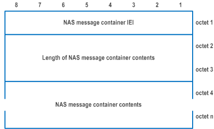
The purpose of the NAS message container IE is to encapsulate a plain 5GS NAS REGISTRATION REQUEST, DEREGISTRATION REQUEST, or SERVICE REQUEST message, or to encapsulate non-cleartext IEs of a CONTROL PLANE SERVICE REQUEST message.
The NAS message container information element is coded as shown in Figure 9.11.3.33.1 and Table 9.11.3.33.1.
The NAS message container is a type 6 information element.

| NAS message container contents (octet 4 to octet n); Max value of 65535 octets | |
| This IE can contain a REGISTRATION REQUEST message as defined in subclause 5.5.1, DEREGISTRATION REQUEST message as defined in subclause 5.5.2.2.1, or a SERVICE REQUEST message as defined in subclause 5.6.1, or non-cleartext IEs of a CONTROL PLANE SERVICE REQUEST message as defined in subclause 5.6.1. | |
9.11.3.34 NAS security algorithms p. 921
The purpose of the NAS security algorithms information element is to indicate the 5G algorithms to be used for ciphering and integrity protection.
The NAS security algorithms information element is coded as shown in Figure 9.11.3.34.1 and Table 9.11.3.34.1.
The NAS security algorithms is a type 3 information element with a length of 2 octets.

| Type of integrity protection algorithm (octet 2, bit 1 to 3) | |
| Bits
4 3 2 1 | |
| 0 0 0 0 | 5G integrity algorithm 5G-IA0 (null integrity protection algorithm) |
| 0 0 0 1 | 5G integrity algorithm 128-5G-IA1 |
| 0 0 1 0 | 5G integrity algorithm 128-5G-IA2 |
| 0 0 1 1 | 5G integrity algorithm 128-5G-IA3 |
| 0 1 0 0 | 5G integrity algorithm 5G-IA4 |
| 0 1 0 1 | 5G integrity algorithm 5G-IA5 |
| 0 1 1 0 | 5G integrity algorithm 5G-IA6 |
| 0 1 1 1 | 5G integrity algorithm 5G-IA7 |
| All other values are reserved. | |
| Type of ciphering algorithm (octet 2, bit 5 to 7) | |
| Bits
8 7 6 5 | |
| 0 0 0 0 | 5G encryption algorithm 5G-EA0 (null ciphering algorithm) |
| 0 0 0 1 | 5G encryption algorithm 128-5G-EA1 |
| 0 0 1 0 | 5G encryption algorithm 128-5G-EA2 |
| 0 0 1 1 | 5G encryption algorithm 128-5G-EA3 |
| 0 0 0 0 | 5G encryption algorithm 5G-EA4 |
| 0 0 0 1 | 5G encryption algorithm 5G-EA5 |
| 0 0 1 0 | 5G encryption algorithm 5G-EA6 |
| 0 0 1 1 | 5G encryption algorithm 5G-EA7 |
| All other values are reserved. | |
9.11.3.35 Network name p. 921
9.11.3.36 Network slicing indication p. 921
The purpose of the Network slicing indication information element is to indicate additional information associated with network slicing in the generic UE configuration update procedure and the registration procedure, other than the user's configured NSSAI, allowed NSSAI, pending NSSAI and rejected NSSAI information.
The Network slicing indication information element is coded as shown in Figure 9.11.3.36.1 and Table 9.11.3.36.1.
The Network slicing indication is a type 1 information element.

| Network slicing subscription change indication (NSSCI) (octet 1, bit 1) | |
| 0 | Network slicing subscription not changed |
| 1 | Network slicing subscription changed |
| Default configured NSSAI indication (DCNI) (octet 1, bit 2) | |
| 0 | Requested NSSAI not created from default configured NSSAI |
| 1 | Requested NSSAI created from default configured NSSAI |
| In the UE to network direction bit 1 is spare. The UE shall set this bit to zero. In the network to UE direction bit 2 is spare. The network shall set this bit to zero. Bits 3 and 4 are spare and shall be coded as zero. | |
9.11.3.36A Non-3GPP NW provided policies p. 922
9.11.3.37 NSSAI p. 922
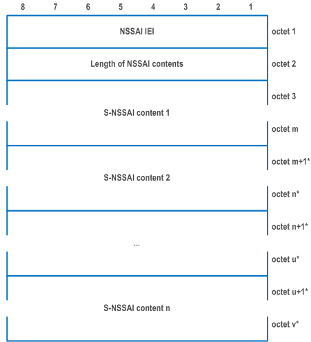
The purpose of the NSSAI information element is to identify a collection of S-NSSAIs
The NSSAI information element is coded as shown in Figure 9.11.3.37.1 and Table 9.11.3.37.1.
The NSSAI is a type 4 information element with a minimum length of 4 octets and a maximum length of 146 octets.

| Value part of the NSSAI information element (octet 3 to v) | |
| The value part of the NSSAI information element consists of one or more S-NSSAI values. Each S-NSSAI value consists of one S-NSSAI and optionally one mapped S-NSSAI. The recipient of this information element shall store the complete list received (NOTE 1, NOTE 2, NOTE 3). If the NSSAI information element conveys an allowed NSSAI and more than 8 S-NSSAI values are included in this information element, the UE shall store the first 8 S-NSSAI values and ignore the remaining octets of the information element. If the NSSAI information element conveys a configured NSSAI (including the default configured NSSAI) or pending NSSAI and more than 16 S-NSSAI values are included in this information element, the UE shall store the first 16 S-NSSAI values and ignore the remaining octets of the information element. | |
| S-NSSAI value: | |
| S-NSSAI value is coded as the length and value part of S-NSSAI information element as specified in subclause 9.11.2.8 starting with the second octet. | |
|
NOTE 1:
The total number of S-NSSAI values in a requested NSSAI shall not exceed eight.
NOTE 2:
The number of S-NSSAI values in an allowed NSSAI shall not exceed eight.
NOTE 3:
The number of S-NSSAI values in a configured NSSAI (including the default configured NSSAI) or pending NSSAI shall not exceed sixteen.
|
9.11.3.37A NSSAI inclusion mode p. 923
The purpose of the NSSAI inclusion mode information element is to indicate the NSSAI inclusion mode in which the UE shall operate.
The NSSAI inclusion mode is a type 1 information element.
The NSSAI inclusion mode information element is coded as shown in Figure 9.11.3.37A.1 and Table 9.11.3.37A.1.

| NSSAI inclusion mode (octet 1, bit 1 to bit 2) | |
| Bits
2 1 | |
| 0 0 | NSSAI inclusion mode A |
| 0 1 | NSSAI inclusion mode B |
| 1 0 | NSSAI inclusion mode C |
| 1 1 | NSSAI inclusion mode D |
9.11.3.38 Operator-defined access category definitions p. 923
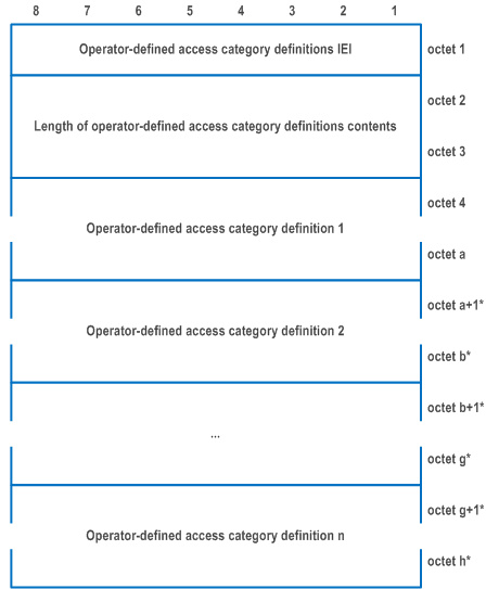
The purpose of the Operator-defined access category definitions information element is to provide the UE with the operator-defined access category definitions or to delete the operator-defined access category definitions at the UE.
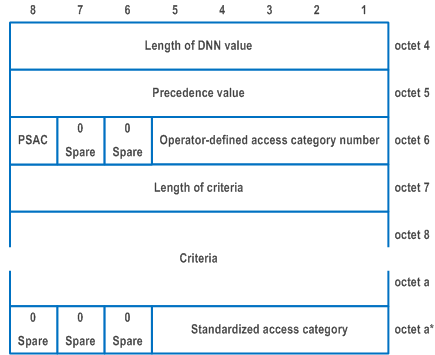
The Operator-defined access category definitions information element is coded as shown in Figure 9.11.3.38.1, Figure 9.11.3.38.2 and Table 9.11.3.38.1.
The Operator-defined access category definitions is a type 6 information element with a minimum length of 3 octets, and maximum length of 8323 octets.


| Value part of the Operator-defined access category definitions information element (octet 4 to h) | |
| The value part of the Operator-defined access category definitions information element consists of zero or no more than 32 operator-defined access category definition fields. Each operator-defined access category definition field is coded as described in Figure 9.11.3.38.2. The length of each operator-defined access category definition field is determined by the length of operator-defined access category definition contents field. | |
| Operator-defined access category definition (octet 4 to octet a): | |
| Length of operator-defined access category definition contents (octet 4) | |
| Length of operator-defined access category definition contents indicates binary coded length of the operator-defined access category definition value field (octet 5 to octet a). | |
| Precedence value (octet 5) | |
| Bits
8 7 6 5 4 3 2 1 | |
| 0 0 0 0 0 0 0 0 | Precedence value 0 |
| to | |
| 1 1 1 1 1 1 1 1 | Precedence value 255 |
| Operator-defined access category number (bits 5 to 1 of octet 6) | |
| Bits
5 4 3 2 1 | |
| 0 0 0 0 0 | Access category number 32 |
| to | |
| 1 1 1 1 1 | Access category number 63 |
| Presence of standardized access category (PSAC) (bit 8 of octet 6) | |
| PSAC field indicates whether the standardized access category field is present or absent. | |
| 0 | Standardized access category field is not included |
| 1 | Standardized access category field is included |
| Length of criteria (octet 7) | |
| Length of criteria field indicates binary coded length of the criteria field. | |
| Criteria (octets 8 to octet a-1) | |
| The criteria field contains one or more criteria components fields. Each criteria component field shall be encoded as a sequence of a one octet criteria type field and zero or more octets criteria value field. The criteria type field shall be transmitted first. | |
| Criteria type | |
| Bits
8 7 6 5 4 3 2 1 | |
| 0 0 0 0 0 0 0 0 | DNN type |
| 0 0 0 0 0 0 0 1 | OS id + OS App Id type |
| 0 0 0 0 0 0 1 0 | S-NSSAI type |
| All other values are reserved. For "DNN type", the criteria value field shall be encoded as a sequence of one octet DNN length-value pair count field and one or more DNN length-value pair fields. The DNN length-value pair count field indicates the number of included DNN length-value pair fields. Each DNN length-value pair field is coded as a sequence of one octet DNN value length field and a DNN value field. The DNN value length field indicates the length in octets of the DNN value field. The DNN value field contains an APN as specified in TS 23.003. For "OS Id + OS App Id type", the criteria value field shall be encoded as a sequence of one octet app id value count field and one or more app id value fields. The app id value count field indicates the number of included app id value fields. Each app id value field is coded as a sequence of a sixteen octet OS id value field, one octet OS app id value length field and an OS app id value field. The OS app id value length field indicates the length in octets of the OS app id value field. The OS id value field contains a Universally Unique IDentifier (UUID) as specified in RFC 4122. The OS app id value field contains an OS specific application identifier. Coding of the OS app id value field is outside the scope of the present document. For "S-NSSAI type", the criteria value field shall be encoded as a sequence of one octet S-NSSAI length-value pair count field and one or more S-NSSAI length-value value fields. The S-NSSAI length-value pair count field indicates the number of included S-NSSAI length-value pair fields. Each S-NSSAI length-value pair field is coded as a sequence of one octet S-NSSAI value length field and an S-NSSAI value field. The S-NSSAI value length field indicates the length in octets of the S-NSSAI value field. The S-NSSAI value field contains one octet SST field optionally followed by three octets SD field. The SST field contains a SST. The SD field contains an SD. SST and SD are specified in TS 23.003. | |
| Standardized access category (bits 5 to 1 of octet a) | |
| Standardized access category field indicates the access category number of the standardized access category that is used in combination with the access identities to determine the establishment cause. | |
| Bits
5 4 3 2 1 | |
| 0 0 0 0 0 | Access category number 0 |
| to | |
| 0 0 1 1 1 | Access category number 7 |
| 0 1 0 0 1 | Access category number 9 |
| 0 1 0 1 0 | Access category number 10 |
| All other values are reserved. | |