Content for TS 24.501 Word version: 18.7.0
1…
3…
4…
4.4…
4.4.3…
4.5…
4.5.3…
4.6…
4.7…
4.9…
4.15…
5…
5.2…
5.3…
5.3.2…
5.3.7…
5.3.19…
5.4…
5.4.1.3…
5.4.2…
5.4.4…
5.4.5…
5.4.6…
5.5…
5.5.1.2.4
5.5.1.2.5…
5.5.1.3…
5.5.1.3.4
5.5.1.3.5…
5.5.2…
5.6…
5.6.2…
6…
6.1.4…
6.2…
6.3…
6.3.2…
6.3.3…
6.4…
6.4.1.4…
6.4.2…
6.5…
7…
8…
8.2.9…
8.3…
9…
9.11.2…
9.11.2.10…
9.11.3…
9.11.3.4…
9.11.3.8…
9.11.3.14…
9.11.3.18C…
9.11.3.29…
9.11.3.33…
9.11.3.39…
9.11.3.45…
9.11.3.50…
9.11.3.53A…
9.11.3.68…
9.11.3.75…
9.11.4…
9.11.4.10…
9.11.4.13…
9.11.4.16…
9.11.4.30…
9.12
10…
A…
B…
C…
D…
D.6…
D.6.3…
D.6.8
D.7…
9.11.4 5GS session management (5GSM) information elements
9.11.4.1 5GSM capability
9.11.4.2 5GSM cause
9.11.4.3 Always-on PDU session indication
9.11.4.4 Always-on PDU session requested
9.11.4.5 Allowed SSC mode
9.11.4.6 Extended protocol configuration options
9.11.4.7 Integrity protection maximum data rate
9.11.4.8 Mapped EPS bearer contexts
9.11.4.9 Maximum number of supported packet filters
...
...
9.11.4 5GS session management (5GSM) information elements p. 1005
9.11.4.1 5GSM capability p. 1005
The purpose of the 5GSM capability information element is to indicate UE capability related to the PDU session management.
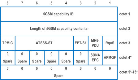
The 5GSM capability information element is coded as shown in Figure 9.11.4.1.1 and Table 9.11.4.1.1.
The 5GSM capability is a type 4 information element with a minimum length of 3 octets and a maximum length of 15 octets.
| 5GSM capability value | |
| RqoS (octet 3, bit 1) | |
| This bit indicates the 5GSM capability to support reflective QoS. | |
| 0 | Reflective QoS not supported |
| 1 | Reflective QoS supported |
| Multi-homed IPv6 PDU session (MH6-PDU) (octet 3, bit 2) | |
| This bit indicates the 5GSM capability for Multi-homed IPv6 PDU session. | |
| 0 | Multi-homed IPv6 PDU session not supported |
| 1 | Multi-homed IPv6 PDU session supported |
| Ethernet PDN type in S1 mode (EPT-S1) (octet 3, bit 3) | |
| This bit indicates UE's 5GSM capability for Ethernet PDN type in S1 mode. | |
| 0 | Ethernet PDN type in S1 mode not supported |
| 1 | Ethernet PDN type in S1 mode supported |
| Supported ATSSS steering functionalities and steering modes (ATSSS-ST) (octet 3, bits 4 to 7) | |
| These bits indicate the 5GSM capability of ATSSS steering functionalities and steering modes | |
| Bits
4 3 2 1 | |
| 0 0 0 0 | ATSSS not supported |
| 0 0 0 1 | ATSSS Low-Layer functionality with any steering mode allowed for ATSSS-LL supported |
| 0 0 1 0 | MPTCP functionality with any steering mode and ATSSS-LL functionality with only active-standby steering mode supported |
| 0 0 1 1 | MPTCP functionality with any steering mode and ATSSS-LL functionality with any steering mode allowed for ATSSS-LL supported |
| 0 1 0 0 | MPQUIC functionality with any steering mode and ATSSS-LL functionality with only active-standby steering mode supported |
| 0 1 0 1 | MPQUIC functionality with any steering mode and ATSSS-LL functionality with any steering mode allowed for ATSSS-LL supported |
| 0 1 1 0 | MPTCP functionality with any steering mode, MPQUIC functionality with any steering mode and ATSSS-LL functionality with any steering mode supported |
| 0 1 1 1 | MPTCP functionality with any steering mode, MPQUIC functionality with any steering mode and ATSSS-LL functionality with any steering mode allowed for ATSSS-LL supported |
| All other values are reserved. | |
| Transfer of port management information containers (TPMIC) (octet 3, bit 8) | |
| This bit indicates the 5GSM capability to support transfer of port management information containers | |
| 0 | Transfer of port management information containers not supported |
| 1 | Transfer of port management information containers supported |
| Access performance measurements per QoS flow rule (APMQF) (octet 4, bit1) | |
| This bit indicates the 5GSM capability to support access performance measurements using the QoS flow of the non default QoS rule, that is used by the service data flow (SDF) traffic. | |
| 0 | Access performance measurements per QoS flow not supported. |
| 1 | Access performance measurements per QoS flow supported. |
| All other bits in octet 4 to 15 are spare and shall be coded as zero, if the respective octet is included in the information element. | |
| Secondary DN authentication and authorization over EPC (SDNAEPC) (octet 4, bit 2) | |
| This bit indicates the 5GSM capability to support secondary DN authentication and authorization over EPC | |
| 0 | Secondary DN authentication and authorization over EPC not supported |
| 1 | Secondary DN authentication and authorization over EPC supported |
| All other bits in octet 4 to 15 are spare and shall be coded as zero, if the respective octet is included in the information element. | |
9.11.4.2 5GSM cause p. 1008
The purpose of the 5GSM cause information element is to indicate the reason why a 5GSM request is rejected.
The 5GSM cause information element is coded as shown in Figure 9.11.4.2.1 and Table 9.11.4.2.1.
The 5GSM cause is a type 3 information element with a length of 2 octets.

| Cause value (octet 2) | |
| Bits
8 7 6 5 4 3 2 1 | |
| 0 0 0 0 1 0 0 0 | Operator determined barring |
| 0 0 0 1 1 0 1 0 | Insufficient resources |
| 0 0 0 1 1 0 1 1 | Missing or unknown DNN |
| 0 0 0 1 1 1 0 0 | Unknown PDU session type |
| 0 0 0 1 1 1 0 1 | User authentication or authorization failed |
| 0 0 0 1 1 1 1 1 | Request rejected, unspecified |
| 0 0 1 0 0 0 0 0 | Service option not supported |
| 0 0 1 0 0 0 0 1 | Requested service option not subscribed |
| 0 0 1 0 0 0 1 1 | PTI already in use |
| 0 0 1 0 0 1 0 0 | Regular deactivation |
| 0 0 1 0 0 1 0 1 | 5GS QoS not accepted |
| 0 0 1 0 0 1 1 0 | Network failure |
| 0 0 1 0 0 1 1 1 | Reactivation requested |
| 0 0 1 0 1 0 0 1 | Semantic error in the TFT operation |
| 0 0 1 0 1 0 1 0 | Syntactical error in the TFT operation |
| 0 0 1 0 1 0 1 1 | Invalid PDU session identity |
| 0 0 1 0 1 1 0 0 | Semantic errors in packet filter(s) |
| 0 0 1 0 1 1 0 1 | Syntactical error in packet filter(s) |
| 0 0 1 0 1 1 1 0 | Out of LADN service area |
| 0 0 1 0 1 1 1 1 | PTI mismatch |
| 0 0 1 1 0 0 1 0 | PDU session type IPv4 only allowed |
| 0 0 1 1 0 0 1 1 | PDU session type IPv6 only allowed |
| 0 0 1 1 0 1 1 0 | PDU session does not exist |
| 0 0 1 1 1 0 0 1 | PDU session type IPv4v6 only allowed |
| 0 0 1 1 1 0 1 0 | PDU session type Unstructured only allowed |
| 0 0 1 1 1 0 1 1 | Unsupported 5QI value |
| 0 0 1 1 1 1 0 1 | PDU session type Ethernet only allowed |
| 0 1 0 0 0 0 1 1 | Insufficient resources for specific slice and DNN |
| 0 1 0 0 0 1 0 0 | Not supported SSC mode |
| 0 1 0 0 0 1 0 1 | Insufficient resources for specific slice |
| 0 1 0 0 0 1 1 0 | Missing or unknown DNN in a slice |
| 0 1 0 1 0 0 0 1 | Invalid PTI value |
| 0 1 0 1 0 0 1 0 | Maximum data rate per UE for user-plane integrity protection is too low |
| 0 1 0 1 0 0 1 1 | Semantic error in the QoS operation |
| 0 1 0 1 0 1 0 0 | Syntactical error in the QoS operation |
| 0 1 0 1 0 1 0 1 | Invalid mapped EPS bearer identity |
| 0 1 0 1 0 1 1 0 | UAS services not allowed |
| 0 1 0 1 1 1 1 1 | Semantically incorrect message |
| 0 1 1 0 0 0 0 0 | Invalid mandatory information |
| 0 1 1 0 0 0 0 1 | Message type non-existent or not implemented |
| 0 1 1 0 0 0 1 0 | Message type not compatible with the protocol state |
| 0 1 1 0 0 0 1 1 | Information element non-existent or not implemented |
| 0 1 1 0 0 1 0 0 | Conditional IE error |
| 0 1 1 0 0 1 0 1 | Message not compatible with the protocol state |
| 0 1 1 0 1 1 1 1 | Protocol error, unspecified |
| Any other value received by the UE shall be treated as 0001 1111, "Request rejected, unspecified". Any other value received by the network shall be treated as 0110 1111, "protocol error, unspecified". | |
9.11.4.3 Always-on PDU session indication p. 1009
The purpose of the Always-on PDU session indication information element is to indicate whether a PDU session is established as an always-on PDU session.
The Always-on PDU session indication information element is coded as shown in Figure 9.11.4.3.1 and Table 9.11.4.3.1.
The Always-on PDU session indication is a type 1 information element.

| Always-on PDU session indication (APSI) (octet 1) | |
| Bit
1 | |
| 0 | Always-on PDU session not allowed |
| 1 | Always-on PDU session required |
| Bits 2, 3 and 4 are spare and shall be coded as zero. | |
9.11.4.4 Always-on PDU session requested p. 1010
The purpose of the Always-on PDU session requested information element is to indicate whether a PDU session is requested to be established as an always-on PDU session.
The Always-on PDU session requested information element is coded as shown in Figure 9.11.4.4.1 and Table 9.11.4.4.1.
The Always-on PDU session requested is a type 1 information element.

| Always-on PDU session requested (APSR) (octet 1) | |
| Bit
1 | |
| 0 | Always-on PDU session not requested |
| 1 | Always-on PDU session requested |
| Bits 2, 3 and 4 are spare and shall be coded as zero. | |
9.11.4.5 Allowed SSC mode p. 1010
The purpose of the Allowed SSC mode information element is to indicate the SSC modes allowed to be used by the UE for the PDU session.
The Allowed SSC mode information element is coded as shown in Figure 9.11.4.5.1 and Table 9.11.4.5.1.
The Allowed SSC mode is a type 1 information element.

| SSC1 (octet 1, bit 1) | |
| Bit
1 | |
| 0 | SSC mode 1 not allowed |
| 1 | SSC mode 1 allowed |
| SSC2 (octet 1, bit 2) | |
| Bit
2 | |
| 0 | SSC mode 2 not allowed |
| 1 | SSC mode 2 allowed |
| SSC3 (octet 1, bit 3) | |
| Bit
3 | |
| 0 | SSC mode 3 not allowed |
| 1 | SSC mode 3 allowed |
| Bit 4 is spare and shall be encoded as zero. | |
9.11.4.6 Extended protocol configuration options p. 1011
9.11.4.7 Integrity protection maximum data rate p. 1011
The purpose of the integrity protection maximum data rate information element is for the UE to indicate to the network the maximum data rate per UE for user-plane integrity protection for uplink and the maximum data rate per UE for user-plane integrity protection for downlink that are supported by the UE.
The integrity protection maximum data rate is coded as shown in Figure 9.11.4.7.1 and Table 9.11.4.7.2.
The integrity protection maximum data rate is a type 3 information element with a length of 3 octets.
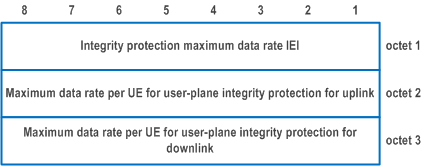
| Maximum data rate per UE for user-plane integrity protection for uplink (octet 2) | |
| Bits
8 7 6 5 4 3 2 1 | |
| 0 0 0 0 0 0 0 0 | 64 kbps (NOTE 3) |
| 0 0 0 0 0 0 0 1 | NULL (NOTE 1) |
| 1 1 1 1 1 1 1 1 | Full data rate (NOTE 2) |
| All other values are spare and shall not be used by a UE compliant to the present version of this specification. If received they shall be interpreted as "64 kbps". | |
| Bits
8 7 6 5 4 3 2 1 | Maximum data rate per UE for user-plane integrity protection for downlink (octet 3) |
| 0 0 0 0 0 0 0 0 | 64 kbps (NOTE 3) |
| 0 0 0 0 0 0 0 1 | NULL (NOTE 1) |
| 1 1 1 1 1 1 1 1 | Full data rate (NOTE 2) |
| All other values are spare and shall not be used by a UE compliant to the present version of this specification. If received they shall be interpreted as "64 kbps". | |
|
NOTE 1:
This value shall be used when N3 data transfer is not supported by the UE or when the UE does not support standalone NR connected to 5GCN.
NOTE 2:
If the UE supports N3 data transfer and supports standalone NR connected to 5GCN (this includes UEs supporting NR-NR dual connectivity, NR-E-UTRA dual connectivity with MN terminated bearers or both of them as described in TS 37.340), then the UE shall use this value.
NOTE 3:
The network can receive this value from a UE compliant to an earlier version of this specification.
|
|
9.11.4.8 Mapped EPS bearer contexts p. 1012
The purpose of the mapped EPS bearer contexts information element is to indicate a set of EPS bearer contexts for a PDU session, as described in subclause 6.1.4.1.
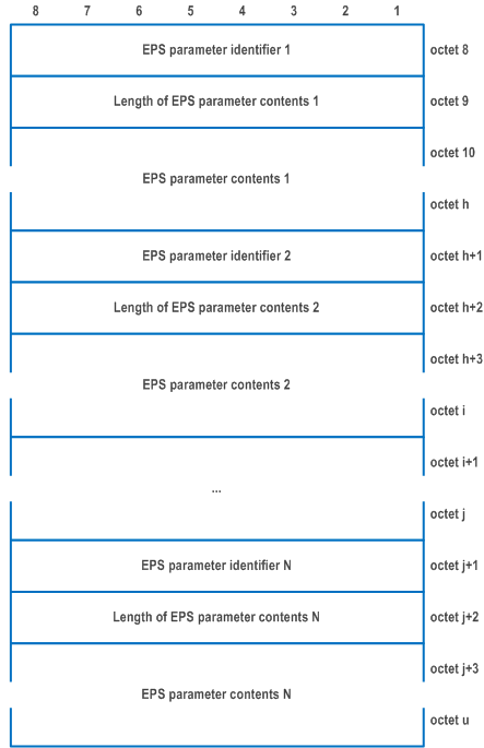
The mapped EPS bearer contexts information element is a type 6 information element with a minimum length of 7 octet and a maximum length of 65538 octets.
The mapped EPS bearer contexts information element is coded as shown in Figure 9.11.4.8.1, Figure 9.11.4.8.2, Figure 9.11.4.8.3 and Table 9.11.4.8.1.
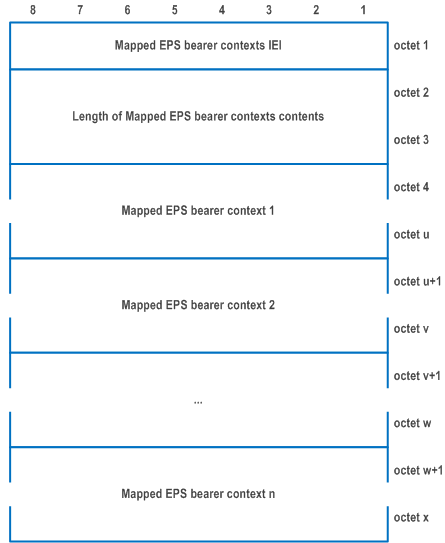
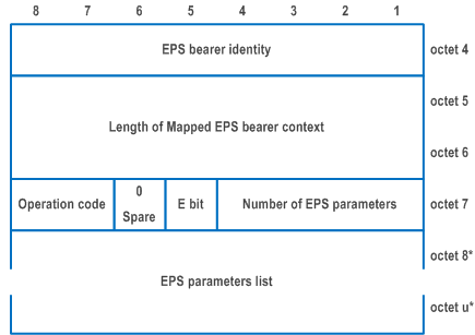
| EPS bearer identity (octet 4) | |
| Bits 5 to 8 contain the EPS bearer identity, and are coded as specified in subclause 9.3.2 of TS 24.301. Bits 1 to 4 are spare and shall be coded as zero. | |
| Operation code (bits 8 to 7 of octet 7) | |
| Bits
8 7 | |
| 0 0 | Reserved |
| 0 1 | Create new EPS bearer |
| 1 0 | Delete existing EPS bearer |
| 1 1 | Modify existing EPS bearer |
| Bit 6 of octet 7 is spare and shall be coded as zero. | |
| E bit (bit 5 of octet 7) | |
| For the "create new EPS bearer" operation, the E bit is encoded as follows: | |
| Bit
5 | |
| 0 | parameters list is not included (NOTE) |
| 1 | parameters list is included |
| For the "modify existing EPS bearer" operation, the E bit is encoded as follows: | |
| Bit
5 | |
| 0 | extension of previously provided parameters list |
| 1 | replacement of all previously provided parameters list |
| If the E bit is set to "parameters list is included", the number of EPS parameters field has non-zero value. If the E bit is set to "extension of previously provided parameters list" or "replacement of previously provided parameters list", the number of parameters field has non-zero value. If the E bit is set to "extension of previously provided parameters" and one of the parameters in the new parameters list already exists in the previously provided parameters, the parameter shall be set to the new value. If the E bit is set to "replacement of all previously provided parameters list" and a parameter in the previously provided parameters is not provided in the new parameters list, the parameter shall be deleted. For the "create new EPS bearer" operation and "delete existing EPS bearer" operation, bit 5 of octet 7 is ignored. | |
| Number of EPS parameters (bits 4 to 1 of octet 7) | |
| The number of EPS parameters contains the binary coding for the number of EPS parameters in the EPS parameters list field. The number of EPS parameters field is encoded in bits 4 through 1 of octet 7 where bit 4 is the most significant and bit 1 is the least significant bit. | |
| EPS parameters list (octets 8 to u) | |
The EPS parameters list contains a variable number of EPS parameters.
Each EPS parameter included in the EPS parameters list is of variable length and consists of:
| |
|
NOTE:
This value shall not be used In this version of the specification.
|
|
9.11.4.9 Maximum number of supported packet filters p. 1016
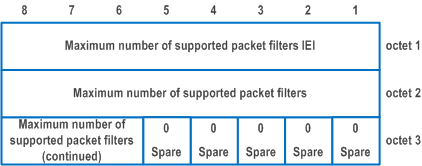
The purpose of the Maximum number of supported packet filters information element is for the UE to indicate to the network the maximum number of packet filters, associated with signaled QoS rules, that can be supported by the UE for the PDU session that is being established, when the PDU session type "IPv4", "IPv6", "IPv4v6" or "Ethernet".
The Maximum number of supported packet filters is coded as shown in Figure 9.11.4.9.1 and Table 9.11.4.9.1.
The Maximum number of supported packet filters is a type 3 information element with a length of 3 octets.
| Maximum number of supported packet filters (octet 2 to 3) | |
| In the Maximum number of supported packet filters field bit 8 of the first octet is the most significant bit and bit 6 of second octet is the least significant bit. Bit 5 to bit 1 of the second octet are spare bits and shall be coded as zero. The number of supported packet filters shall be in the range of 17 to 1024. | |