Content for TS 24.501 Word version: 18.7.0
1…
3…
4…
4.4…
4.4.3…
4.5…
4.5.3…
4.6…
4.7…
4.9…
4.15…
5…
5.2…
5.3…
5.3.2…
5.3.7…
5.3.19…
5.4…
5.4.1.3…
5.4.2…
5.4.4…
5.4.5…
5.4.6…
5.5…
5.5.1.2.4
5.5.1.2.5…
5.5.1.3…
5.5.1.3.4
5.5.1.3.5…
5.5.2…
5.6…
5.6.2…
6…
6.1.4…
6.2…
6.3…
6.3.2…
6.3.3…
6.4…
6.4.1.4…
6.4.2…
6.5…
7…
8…
8.2.9…
8.3…
9…
9.11.2…
9.11.2.10…
9.11.3…
9.11.3.4…
9.11.3.8…
9.11.3.14…
9.11.3.18C…
9.11.3.29…
9.11.3.33…
9.11.3.39…
9.11.3.45…
9.11.3.50…
9.11.3.53A…
9.11.3.68…
9.11.3.75…
9.11.4…
9.11.4.10…
9.11.4.13…
9.11.4.16…
9.11.4.30…
9.12
10…
A…
B…
C…
D…
D.6…
D.6.3…
D.6.8
D.7…
9.11.4.16 SSC mode
9.11.4.17 Re-attempt indicator
9.11.4.18 5GSM network feature support
9.11.4.20 Serving PLMN rate control
9.11.4.21 5GSM congestion re-attempt indicator
9.11.4.22 ATSSS container
9.11.4.23 Control plane only indication
9.11.4.24 IP header compression configuration
9.11.4.25 DS-TT Ethernet port MAC address
9.11.4.26 UE-DS-TT residence time
9.11.4.27 Port management information container
9.11.4.28 Ethernet header compression configuration
9.11.4.29 Remote UE context list
...
...
9.11.4.16 SSC mode p. 1035
The purpose of the SSC mode information element is to indicate SSC mode.
The SSC mode information element is coded as shown in Figure 9.11.4.16.1 and Table 9.11.4.16.1.
The SSC mode is a type 1 information element.

| SSC mode value (octet 1, bit 1 to bit 4) | |
| Bits
3 2 1 | |
| 0 0 1 | SSC mode 1 |
| 0 1 0 | SSC mode 2 |
| 0 1 1 | SSC mode 3 |
| 1 0 0 | unused; shall be interpreted as "SSC mode 1", if received by the network |
| 1 0 1 | unused; shall be interpreted as "SSC mode 2", if received by the network |
| 1 1 0 | unused; shall be interpreted as "SSC mode 3", if received by the network |
| All other values are reserved. | |
9.11.4.17 Re-attempt indicator |R16| p. 1035
The purpose of the Re-attempt indicator information element is to indicate a condition under which the UE is allowed in the current PLMN or its equivalent PLMN(s) or the current SNPN or its equivalent SNPNs for the same DNN, to re-attempt a session management procedure (see TS 24.301) corresponding to the 5GS session management procedure which was rejected by the network.
The Re-attempt indicator information element is coded as shown in Figure 9.11.4.17.1 and Table 9.11.4.17.1.
The Re-attempt indicator is a type 4 information element with a length of 3 octets.

| RATC (octet 3, bit 1) | |
| 0 | UE is allowed to re-attempt the procedure in S1 mode |
| 1 | UE is not allowed to re-attempt the procedure in S1 mode |
| EPLMNC (octet 3, bit 2) | |
| 0 | UE is allowed to re-attempt the procedure in an equivalent PLMN or equivalent SNPN |
| 1 | UE is not allowed to re-attempt the procedure in an equivalent PLMN or equivalent SNPN |
| Bits 3 to 8 of octet 3 are spare and shall be encoded as zero. | |
9.11.4.18 5GSM network feature support |R16| p. 1036
The purpose of the 5GSM network feature support information element is to indicate whether certain session management related features are supported by the network.
The 5GSM network feature support information element is coded as shown in Figure 9.11.4.18.1 and Table 9.11.4.18.1.
The 5GSM network feature support is a type 4 information element with a minimum length of 3 octets and a maximum length of 15 octets.
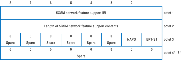
| 5GSM network feature support contents | |
| Ethernet PDN type in S1 mode (IEPT-S1) (octet 3, bit 1) | |
| This bit indicates network's capability for Ethernet PDN type in S1 mode. | |
| 0 | Ethernet PDN type in S1 mode not supported |
| 1 | Ethernet PDN type in S1 mode supported |
| Non-3GPP access path switching (NAPS) (octet 3, bit 2) | |
| This bit indicates whether non-3GPP access path switching is supported. | |
| 0 | non-3GPP access path switching not supported |
| 1 | non-3GPP access path switching supported |
| All other bits in octet 3 to 15 are spare and shall be coded as zero, if the respective octet is included in the information element. | |
9.11.4.19 Void
9.11.4.20 Serving PLMN rate control |R16| p. 1037
9.11.4.21 5GSM congestion re-attempt indicator |R16| p. 1037
The purpose of the 5GSM congestion re-attempt indicator information element is to indicate whether the back-off timer is applied in the registered PLMN or all PLMNs or in the registered SNPN or all equivalent SNPNs, and additionally to indicate whether the back-off timer is applied in the current access type or both 3GPP access type and non-3GPP access type.
The 5GSM congestion re-attempt indicator information element is coded as shown in Figure 9.11.4.21.1 and Table 9.11.4.21.1.
The 5GSM congestion re-attempt indicator is a type 4 information element with a length of 3 octets.

| ABO (All PLMNs Back-off timer) (octet 3, bit 1) | |
| 0 | The back-off timer is applied in the registered PLMN or registered SNPN. |
| 1 | The back-off timer is applied in all PLMNs or all equivalent SNPNs. |
| CATBO (Current Access Type Back-off Timer) (octet 3, bit 2) | |
| 0 | The back-off timer is applied in both 3GPP access type and non-3GPP access type |
| 1 | The back-off timer is applied in the current access type. |
| Bits 3 to 8 of octet 3 are spare and shall be encoded as zero. | |
9.11.4.22 ATSSS container |R16| p. 1037
The purpose of the ATSSS container information element is to transfer parameters associated with ATSSS.
The ATSSS container information element is coded as shown in Figure 9.11.4.22.1 and Table 9.11.4.22.1.
The ATSSS container is a type 6 information element with a minimum length of 3 octets and a maximum length of 65538 octets.
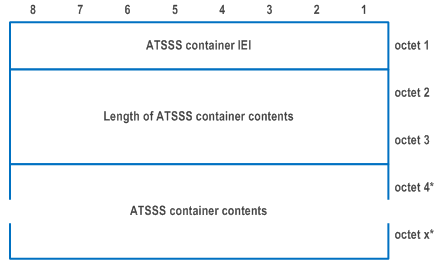
| ATSSS container contents are defined in TS 24.193. | |
9.11.4.23 Control plane only indication |R16| p. 1038
The purpose of the control plane only indication information element is to indicate that a PDU session is only for control plane CIoT 5GS optimization.
The control plane only indication information element is coded as shown in Figure 9.11.4.23.1.
The control plane only indication is a type 1 information element.

| Control plane only indication value (CPOI) (octet 1) | |
| Bit
1 | |
| 0 | reserved |
| 1 | PDU session can be used for control plane CIoT 5GS optimization only |
| The value 0 is reserved. If received, it shall be interpreted as if the control plane only indication IE was not included in the message. Bits 4 to 2 of octet 1 are spare and shall be all encoded as zero. | |
9.11.4.24 IP header compression configuration |R16| p. 1038
The purpose of the IP header compression configuration information element is to negotiate ROHC channel setup parameters specified in RFC 5795 and, optionally, provide additional header compression context setup parameters.
The IP header compression configuration information element is coded as shown in Figure 9.11.4.24.1 and Table 9.11.4.24.1.
The IP header compression configuration is a type 4 information element with a minimum length of 5 octets and a maximum length of 257 octets.
The optional Additional IP header compression parameters container field conveys the additional header compression context setup parameters as specified in TS 23.501 in a generic container. This field corresponds to the profile-specific information in the header of the ROHC IR packet type in RFC 5795.
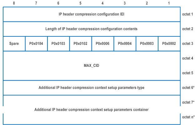
| ROHC Profiles (octet 3) | |||||||||
| The ROHC Profiles shall indicate which of the ROHC profiles is supported. When a particular bit is set to 1, this indicates that the corresponding profile is supported. The No Compression profile 0x0000 (see RFC 5795) shall always be supported. When all the bits are set to 0, this indicates that only the No Compression profile 0x0000 is supported. | |||||||||
| Profile 0x0002 support indicator (see RFC 3095 and RFC 4815) (octet 3 bit 1) | |||||||||
| 0 | RoHC profile 0x0002 (UDP/IP) is not supported | ||||||||
| 1 | RoHC profile 0x0002 (UDP/IP) is supported | ||||||||
| Profile 0x0003 support indicator (see RFC 3095 and RFC 4815) (octet 3 bit 2) | |||||||||
| 0 | RoHC profile 0x0003 (ESP/IP) is not supported | ||||||||
| 1 | RoHC profile 0x0003 (ESP/IP) is supported | ||||||||
| Profile 0x0004 support indicator (see RFC 3843 and RFC 4815) (octet 3 bit 3) | |||||||||
| 0 | RoHC profile 0x0004 (IP) is not supported | ||||||||
| 1 | RoHC profile 0x0004 (IP) is supported | ||||||||
| Profile 0x0006 support indicator (see RFC 6846) (octet 3 bit 4) | |||||||||
| 0 | RoHC profile 0x0006 (TCP/IP) is not supported | ||||||||
| 1 | RoHC profile 0x0006 (TCP/IP) is supported | ||||||||
| Profile 0x0102 support indicator (see RFC 5225) (octet 3 bit 5) | |||||||||
| 0 | RoHC profile 0x0102 (UDP/IP) is not supported | ||||||||
| 1 | RoHC profile 0x0102 (UDP/IP) is supported | ||||||||
| Profile 0x0103 support indicator (see RFC 5225) (octet 3 bit 6) | |||||||||
| 0 | RoHC profile 0x0103 (ESP/IP) is not supported | ||||||||
| 1 | RoHC profile 0x0103 (ESP/IP) is supported | ||||||||
| Profile 0x0104 support indicator (see RFC 5225) (octet 3 bit 7) | |||||||||
| 0 | RoHC profile 0x0104 (IP) is not supported | ||||||||
| 1 | RoHC profile 0x0104 (IP) is supported | ||||||||
| Bit 8 is spare and shall be set to 0. | |||||||||
| MAX_CID (octet 4 and octet 5) | |||||||||
| This is the MAX_CID value as specified in TS 36.323. It is encoded in binary coding with a value in the range from 1 to 16383. | |||||||||
| Additional IP header compression context parameters type (octet 6). | |||||||||
| The Additional IP header compression context parameters type octet indicates the profile associated with the profile-specific information in the Additional IP header compression context parameters container. | |||||||||
| Bits
8 7 6 5 4 3 2 1 | |||||||||
| 0 0 0 0 0 0 0 0 | 0x0000 (No Compression) | ||||||||
| 0 0 0 0 0 0 0 1 | 0x0002 (UDP/IP) | ||||||||
| 0 0 0 0 0 0 1 0 | 0x0003 (ESP/IP) | ||||||||
| 0 0 0 0 0 0 1 1 | 0x0004 (IP) | ||||||||
| 0 0 0 0 0 1 0 0 | 0x0006 (TCP/IP) | ||||||||
| 0 0 0 0 0 1 0 1 | 0x0102 (UDP/IP) | ||||||||
| 0 0 0 0 0 1 1 0 | 0x0103 (ESP/IP) | ||||||||
| 0 0 0 0 0 1 1 1 | 0x0104 (IP) | ||||||||
| 0 0 0 0 1 0 0 0 | Other | ||||||||
| 0 0 0 0 1 0 0 1 | |||||||||
| to | Spare | ||||||||
| 1 1 1 1 1 1 1 1 | |||||||||
| Additional IP header compression context parameters container (octets 7 to n). | |||||||||
| Additional IP header compression context parameters container carries the profile-specific information (see RFC 5795). The maximum size is 251 octets. | |||||||||
|
NOTE:
If the Additional IP header compression context setup parameters container is included, then the Additional IP header compression context parameters type shall be included in the octet 6.
|
|||||||||
9.11.4.25 DS-TT Ethernet port MAC address |R16| p. 1042
The purpose of the DS-TT Ethernet port MAC address information element is to signal the MAC address of the DS-TT Ethernet port used for a PDU session of "Ethernet" PDU session type.
The DS-TT Ethernet port MAC address information element is coded as shown in Figure 9.11.4.25.1 and Table 9.11.4.25.1.
The DS-TT Ethernet port MAC address is a type 4 information element with a length of 8 octets.
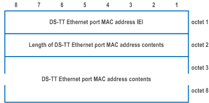
| DS-TT Ethernet port MAC address contents (octets 3 to 8) | |
| The DS-TT Ethernet port MAC address contents consist of the binary representation of the MAC address of the DS-TT Ethernet port used for the PDU session, starting with the LSB bit of the first octet of the MAC address included in bit 1 of octet 3. | |
9.11.4.26 UE-DS-TT residence time |R16| p. 1042
The purpose of the UE-DS-TT residence time information element is to signal the time taken within the UE and the DS-TT to forward a packet i.e. between the ingress of the UE and the DS-TT port in the DL direction, or between the DS-TT port and the egress of the UE in the UL direction.
The UE- DS-TT residence time information element is coded as shown in Figure 9.11.4.26.1 and Table 9.11.4.26.1.
The UE-DS-TT residence time is a type 4 information element with a length of 10 octets.
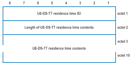
| UE-DS-TT residence time contents (octets 3 to 10) | |
| The UE-DS-TT residence time contents contain the UE-DS-TT residence time encoded as specified for the correctionField in IEEE Std 1588-2019 [43B], with the LSB bit of the first octet of the UE-DS-TT residence time included in bit 1 of octet 3. If the UE-DS-TT residence time.is too big to be represented, all bits of octets 3 to 10 shall be coded as "1" except the MSB bit of octet 10. | |
9.11.4.27 Port management information container |R16| p. 1043
The purpose of the Port management information container information element is to transport a port management service message as specified in clause 8 of TS 24.539.
The Port management information container information element is coded as shown in Figure 9.11.4.27.1 and Table 9.11.4.27.1.
The Port management information container is a type 6 information element with a minimum length of 4 octets and a maximum length of 65538 octets.
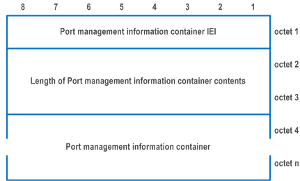
| Port management information container (octet 4 to n) | |
| A port management service message as specified in clause 8 of TS 24.539. | |
9.11.4.28 Ethernet header compression configuration |R16| p. 1043
The purpose of the Ethernet header compression configuration information element is to negotiate the use of EHC and the length of the CID field in the EHC packet (see TS 38.323).
The Ethernet header compression configuration information element is coded as shown in Figure 9.11.4.28.1 and Table 9.11.4.28.1.
The Ethernet header compression configuration is a type 4 information element with the length of 3 octets.
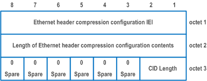
| Length of CID field value (CID Length) (octet 3 bits 1 and 2) | |
| Bits
2 1 | |
| 0 0 | Ethernet header compression not used |
| 0 1 | 7 bits |
| 1 0 | 15 bits |
| All other values shall be interpreted as "7 bits". Bits 3 to 8 of octet 3 are spare and shall be coded as zero. | |
9.11.4.29 Remote UE context list |R17| p. 1044
The purpose of the Remote UE context list information element is to provide identity and optionally IP address of a 5G ProSe remote UE connected to, or disconnected from, a UE acting as a 5G ProSe layer-3 UE-to-network relay.
The Remote UE context list information element is coded as shown in Figure 9.11.4.29.1, Figure 9.11.4.29.2, Table 9.11.4.29.1 and Table 9.11.4.29.2.
The Remote UE context list is a type 6 information element with a minimum length of 16 octets and a maximum length of 65538 octets.
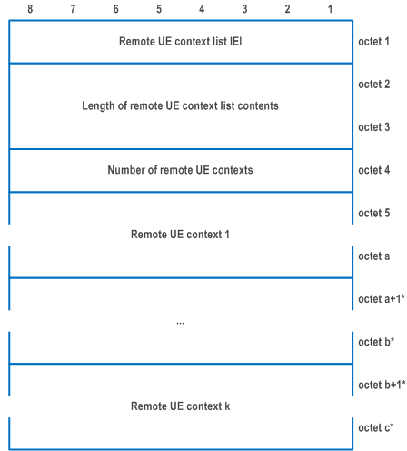
| Remote UE context (octet 5 etc) | |
| The contents of remote UE context are applicable for one individual UE and are coded as shown in Figure 9.11.4.29.2 and Table 9.11.4.29.2. | |
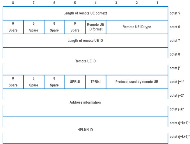
| Remote UE ID type (bits 1 to 3 of octet 6) | |
| Bits
3 2 1 | |
| 0 0 0 | UP-PRUK ID |
| 0 1 0 | CP-PRUK ID |
| 0 1 1 | IMEI |
| 1 0 0 | IMEISV |
| All other values are reserved. | |
| Remote UE ID format (bit 4 of octet 6) (NOTE) | |
| Bit
4 | |
| 0 | Network access identifier (NAI) |
| 1 | 64-bit string |
| Bits 5 to 8 of octet 6 are spare and shall be coded as zero. | |
| The length of remote UE ID field contains the binary coded representation of the length of the remote UE ID field. The first bit in transmission order is the most significant bit. | |
| Remote UE ID (octet 8 to octet j) | |
| The UP-PRUK ID as specified in TS 33.503, the CP-PRUK ID as specified in TS 33.503, the IMEI or the IMEISV of the 5G ProSe Remote UE. If the remote UE ID type field indicates "UP-PRUK ID" or "CP-PRUK ID", and the remote UE ID format field indicates "NAI", the remote UE ID field contains the UP-PRUK ID or the CP-PRUK ID in the NAI format as defined in TS 23.003, encoded as UTF-8 string. If the remote UE ID type field indicates "UP-PRUK ID", and the remote UE ID format field indicates "64-bit string", the remote UE ID field contains the UP-PRUK ID as a 64-bit string, encoded using binary encoding. If the remote UE ID type field indicates "IMEI" or "IMEISV", the remote UE ID field contains the IMEI or the IMEISV encoded as 5GS mobile identity information element for type of identity "IMEI" or "IMEISV" as specified in subclause 9.11.3.4, starting with the fourth octet. | |
| Protocol used by remote UE (octet j+1, bits 1 to 3) | |
| Bits
3 2 1 | |
| 0 0 0 | No IP info |
| 0 0 1 | IPv4 |
| 0 1 0 | IPv6 |
| 1 0 0 | Unstructured |
| 1 0 1 | Ethernet |
| All other values are reserved. | |
| TCP port range for IPv4 indicator (TPRI4I) (octet j+1, bits 4) | |
| Bit
4 | |
| 0 | TCP port range for IPv4 absent |
| 1 | TCP port range for IPv4 present |
| UDP port range for IPv4 indicator (UPRI4I) (octet j+1, bits 5) | |
| Bit
5 | |
| 0 | UDP port range for IPv4 absent |
| 1 | UDP port range for IPv4 present |
| Bits 6 to 8 of octet j+1 are spare and shall be coded as zero. | |
If the Protocol used by remote UE indicates IPv4 and:
| |
|
NOTE:
In the present release of the specification, providing information for IP protocols other than UDP or TCP is not specified.
|
|