Content for TS 24.501 Word version: 18.7.0
1…
3…
4…
4.4…
4.4.3…
4.5…
4.5.3…
4.6…
4.7…
4.9…
4.15…
5…
5.2…
5.3…
5.3.2…
5.3.7…
5.3.19…
5.4…
5.4.1.3…
5.4.2…
5.4.4…
5.4.5…
5.4.6…
5.5…
5.5.1.2.4
5.5.1.2.5…
5.5.1.3…
5.5.1.3.4
5.5.1.3.5…
5.5.2…
5.6…
5.6.2…
6…
6.1.4…
6.2…
6.3…
6.3.2…
6.3.3…
6.4…
6.4.1.4…
6.4.2…
6.5…
7…
8…
8.2.9…
8.3…
9…
9.11.2…
9.11.2.10…
9.11.3…
9.11.3.4…
9.11.3.8…
9.11.3.14…
9.11.3.18C…
9.11.3.29…
9.11.3.33…
9.11.3.39…
9.11.3.45…
9.11.3.50…
9.11.3.53A…
9.11.3.68…
9.11.3.75…
9.11.4…
9.11.4.10…
9.11.4.13…
9.11.4.16…
9.11.4.30…
9.12
10…
A…
B…
C…
D…
D.6…
D.6.3…
D.6.8
D.7…
9.11.3.68 UE radio capability ID
9.11.3.69 UE radio capability ID deletion indication
9.11.3.70 Truncated 5G-S-TMSI configuration
9.11.3.71 WUS assistance information
9.11.3.72 N5GC indication
9.11.3.73 NB-N1 mode DRX parameters
9.11.3.74 Additional configuration indication
...
...
9.11.3.68 UE radio capability ID |R16| p. 965
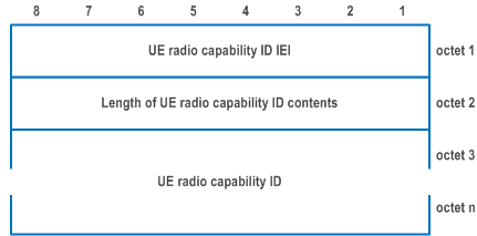
The purpose of the UE radio capability ID information element is to carry a UE radio capability ID.
The UE radio capability ID information element is coded as shown in Figure 9.11.3.68.1 and Table 9.11.3.68.1.
The UE radio capability ID is a type 4 information element with a length of n octets.

| UE radio capability ID (octets 3 to n) | |
| The UE radio capability ID contents contain the UE radio capability ID as specified in TS 23.003, with each hexadecimal digit coded over 4 bits, starting with the first hexadecimal digit coded in bits 4 to 1 of octet 3, the second hexadecimal digit coded in bits 8 to 5 of octet 3, and so on. If the UE radio capability ID contains an odd number of hexadecimal digits, bits 8 to 5 of the last octet (octet n) shall be coded as "1111". | |
9.11.3.69 UE radio capability ID deletion indication |R16| p. 965
The purpose of the UE radio capability ID deletion indication information element is to indicate to the UE that deletion of UE radio capability IDs is requested.
The UE radio capability ID deletion indication is a type 1 information element.
The UE radio capability ID deletion indication information element is coded as shown in Figure 9.11.3.69.1 and Table 9.11.3.69.1.

| Deletion requested (octet 1) | |
| Bits
3 2 1 | |
| 0 0 0 | UE radio capability ID deletion not requested |
| 0 0 1 | Network-assigned UE radio capability IDs deletion requested |
| All other values are unused and shall be interpreted as "UE radio capability ID deletion not requested", if received by the UE. | |
9.11.3.70 Truncated 5G-S-TMSI configuration |R16| p. 966
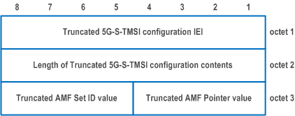
The purpose of the Truncated 5G-S-TMSI configuration information element is to provide the size of the components of the truncated 5G-S-TMSI to the UE in NB-N1 mode to create the truncated 5G-S-TMSI.
The Truncated 5G-S-TMSI configuration information element is coded as shown in Figure 9.11.3.70.1 and Table 9.11.3.70.1.
The Truncated 5G-S-TMSI configuration is a type 4 information element with 3 octets length.

| Truncated AMF Pointer value (bits 4 to 1 of octet 3) | |
| This field represents the size of the least significant bits of the AMF Pointer. | |
| Bits
4 3 2 1 | |
| 0 0 0 0 | reserved |
| 0 0 0 1 | 1 least significant bit of the AMF Pointer |
| 0 0 1 0 | 2 least significant bits of the AMF Pointer |
| 0 0 1 1 | 3 least significant bits of the AMF Pointer |
| 0 1 0 0 | 4 least significant bits of the AMF Pointer |
| 0 1 0 1 | 5 least significant bits of the AMF Pointer |
| 0 1 1 0 | 6 least significant bits of the AMF Pointer |
| All other values shall be interpreted as "6 least significant bits of the AMF Pointer" by this version of the protocol. | |
| Truncated AMF Set ID value (bits 8 to 5 of octet 3) | |
| This field represents the size of the least significant bits of the AMF Set ID. | |
| Bits
4 3 2 1 | |
| 0 0 0 0 | reserved |
| 0 0 0 1 | 1 least significant bit of the AMF Set ID |
| 0 0 1 0 | 2 least significant bits of the AMF Set ID |
| 0 0 1 1 | 3 least significant bits of the AMF Set ID |
| 0 1 0 0 | 4 least significant bits of the AMF Set ID |
| 0 1 0 1 | 5 least significant bits of the AMF Set ID |
| 0 1 1 0 | 6 least significant bits of the AMF Set ID |
| 0 1 1 1 | 7 least significant bits of the AMF Set ID |
| 1 0 0 0 | 8 least significant bits of the AMF Set ID |
| 1 0 0 1 | 9 least significant bits of the AMF Set ID |
| 1 0 1 0 | 10 least significant bits of the AMF Set ID |
| All other values shall be interpreted as "10 least significant bits of the AMF Set ID" by this version of the protocol. | |
| NOTE: | |
9.11.3.71 WUS assistance information |R16| p. 967
9.11.3.72 N5GC indication |R16| p. 967
The purpose of the N5GC indication information element is to indicate to the network that the registration request by the W-AGF is on behalf of an N5GC device.
The N5GC indication information element is coded as shown in Figure 9.11.3.72.1.
The N5GC indication is a type 1 information element.

| N5GC device indication bit (N5GCREG) (octet 1, bit 1) | |
| 0 | N5GC device registration is not requested |
| 1 | N5GC device registration is requested |
| Bits 2 to 4 are spare and shall be coded as zero. | |
9.11.3.73 NB-N1 mode DRX parameters |R16| p. 968
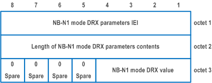
The purpose of the NB-N1 mode DRX parameters information element is to indicate that the UE wants to use DRX in NB-N1 mode and for the network to indicate the DRX cycle value to be used at paging in NB-N1 mode.
The NB-N1 mode DRX parameters is a type 4 information element with a length of 3 octets.
The NB-N1 mode DRX parameters information element is coded as shown in Figure 9.11.3.73.1 and Table 9.11.3.73.1.
The value part of a DRX parameter information element is coded as shown in Table 9.11.3.73.1.

| NB-N1 mode DRX value (octet 3, bits 1 to 4) | |
| This field represents the DRX cycle parameter 'T', for NB-N1 mode, as defined in TS 36.304. | |
| Bits
4 3 2 1 | |
| 0 0 0 0 | DRX value not specified |
| 0 0 0 1 | DRX cycle parameter T = 32 |
| 0 0 1 0 | DRX cycle parameter T = 64 |
| 0 0 1 1 | DRX cycle parameter T = 128 |
| 0 1 0 0 | DRX cycle parameter T = 256 |
| 0 1 0 1 | DRX cycle parameter T = 512 |
| 0 1 1 0 | DRX cycle parameter T = 1024 |
| All other values shall be interpreted as "DRX value not specified" by this version of the protocol. Bits 5 to 8 of octet 3 are spare and shall be coded as zero. | |
9.11.3.74 Additional configuration indication |R16| p. 968
The purpose of the Additional configuration indication information element is to indicate additional information associated with the generic UE configuration update procedure.
The Additional configuration indication information element is coded as shown in Figure 9.11.3.74.1 and Table 9.11.3.74.1.
The Additional configuration indication is a type 1 information element.

| Signalling connection maintain request (SCMR) (octet 1, bit 1) | |
| 0 | no additional information |
| 1 | release of N1 NAS signalling connection not required |
| Bits 2 to 4 are spare and shall be coded as zero. | |