Content for TS 24.501 Word version: 18.7.0
1…
3…
4…
4.4…
4.4.3…
4.5…
4.5.3…
4.6…
4.7…
4.9…
4.15…
5…
5.2…
5.3…
5.3.2…
5.3.7…
5.3.19…
5.4…
5.4.1.3…
5.4.2…
5.4.4…
5.4.5…
5.4.6…
5.5…
5.5.1.2.4
5.5.1.2.5…
5.5.1.3…
5.5.1.3.4
5.5.1.3.5…
5.5.2…
5.6…
5.6.2…
6…
6.1.4…
6.2…
6.3…
6.3.2…
6.3.3…
6.4…
6.4.1.4…
6.4.2…
6.5…
7…
8…
8.2.9…
8.3…
9…
9.11.2…
9.11.2.10…
9.11.3…
9.11.3.4…
9.11.3.8…
9.11.3.14…
9.11.3.18C…
9.11.3.29…
9.11.3.33…
9.11.3.39…
9.11.3.45…
9.11.3.50…
9.11.3.53A…
9.11.3.68…
9.11.3.75…
9.11.4…
9.11.4.10…
9.11.4.13…
9.11.4.16…
9.11.4.30…
9.12
10…
A…
B…
C…
D…
D.6…
D.6.3…
D.6.8
D.7…
9.11.4.13 QoS rules p. 1025
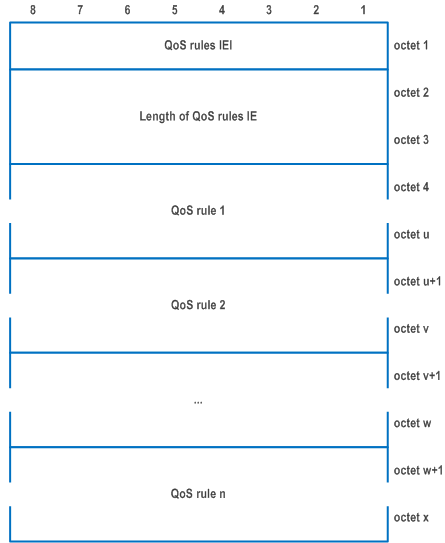
The purpose of the QoS rules information element is to indicate a set of QoS rules to be used by the UE, where each QoS rule is a set of parameters as described in subclause 6.2.5.1.1.2:
- for classification and marking of uplink user traffic; and
- for identification of a QoS flow which the network is to use for a particular downlink user traffic.
| QoS rule identifier (octet 4) | |
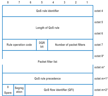
| The QoS rule identifier field is used to identify the QoS rule. | |
| Bits
8 7 6 5 4 3 2 1 | |
| 0 0 0 0 0 0 0 0 | no QoS rule identifier assigned |
| 0 0 0 0 0 0 0 1 | QRI 1 |
| to | |
| 1 1 1 1 1 1 1 1 | QRI 255 |
| The network shall not set the QRI value to 0. | |
| QoS rule precedence (octet m+1) | |
| The QoS rule precedence field is used to specify the precedence of the QoS rule among all QoS rules (both the signalled QoS rules as described in subclause 6.2.5.1.1.2 and the derived QoS rules as described in subclause 6.2.5.1.1.3) associated with the PDU session of the QoS flow. This field includes the binary coded value of the QoS rule precedence in the range from 0 to 255 (decimal). The higher the value of the QoS rule precedence field, the lower the precedence of that QoS rule is. For the "delete existing QoS rule" operation, the QoS rule precedence value field shall not be included. For the "create new QoS rule" operation, the QoS rule precedence value field shall be included. The value 80 (decimal) is reserved. | |
| Segregation bit (bit 7 of octet m+2) (see NOTE 1) | |
| In the UE to network direction the segregation bit indicates whether the UE is requesting the network to bind service data flows described by the QoS rule to a dedicated QoS Flow and it is encoded as follows. In the network to UE direction this bit is spare. | |
| 0 | Segregation not requested |
| 1 | Segregation requested |
| QoS flow identifier (QFI) (bits 6 to 1 of octet m+2) (see NOTE 1) | |
| The QoS flow identifier (QFI) field contains the QoS flow identifier. | |
| Bits
6 5 4 3 2 1 | |
| 0 0 0 0 0 0 | no QoS flow identifier assigned |
| 0 0 0 0 0 1 | QFI 1 |
| to | |
| 1 1 1 1 1 1 | QFI 63 |
| The network shall not set the QFI value to 0. For the "delete existing QoS rule" operation, the QoS flow identifier value field shall not be included. For the "create new QoS rule" operation, the QoS flow identifier value field shall be included. | |
| DQR bit (bit 5 of octet 7) | |
| The DQR bit indicates whether the QoS rule is the default QoS rule and it is encoded as follows: | |
| 0 | the QoS rule is not the default QoS rule. |
| 1 | the QoS rule is the default QoS rule. |
| Rule operation code (bits 8 to 6 of octet 7) | |
| Bits
8 7 6 | |
| 0 0 0 | Reserved |
| 0 0 1 | Create new QoS rule |
| 0 1 0 | Delete existing QoS rule |
| 0 1 1 | Modify existing QoS rule and add packet filters |
| 1 0 0 | Modify existing QoS rule and replace all packet filters |
| 1 0 1 | Modify existing QoS rule and delete packet filters |
| 1 1 0 | Modify existing QoS rule without modifying packet filters |
| 1 1 1 | Reserved |
| Number of packet filters (bits 4 to 1 of octet 7) | |
| The number of packet filters contains the binary coding for the number of packet filters in the packet filter list. The number of packet filters field is encoded in bits 4 through 1 of octet 7 where bit 4 is the most significant and bit 1 is the least significant bit. For the "delete existing QoS rule" operation and for the "modify existing QoS rule without modifying packet filters" operation, the number of packet filters shall be coded as 0. For the "create new QoS rule" operation and the "modify existing QoS rule and replace all packet filters" operation, the number of packet filters shall be greater than or equal to 0 and less than or equal to 15. For all other operations, the number of packet filters shall be greater than 0 and less than or equal to 15. | |
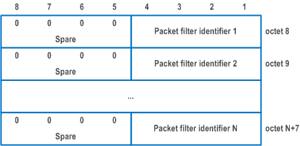
| Packet filter list (octets 8 to m) | |
The packet filter list contains a variable number of packet filters.
For the "delete existing QoS rule" operation, the length of QoS rule field is set to one.
For the "delete existing QoS rule" operation and the "modify existing QoS rule without modifying packet filters" operation, the packet filter list shall be empty.
For the "modify existing QoS rule and delete packet filters" operation, the packet filter list shall contain a variable number of packet filter identifiers. This number shall be derived from the coding of the number of packet filters field in octet 7.
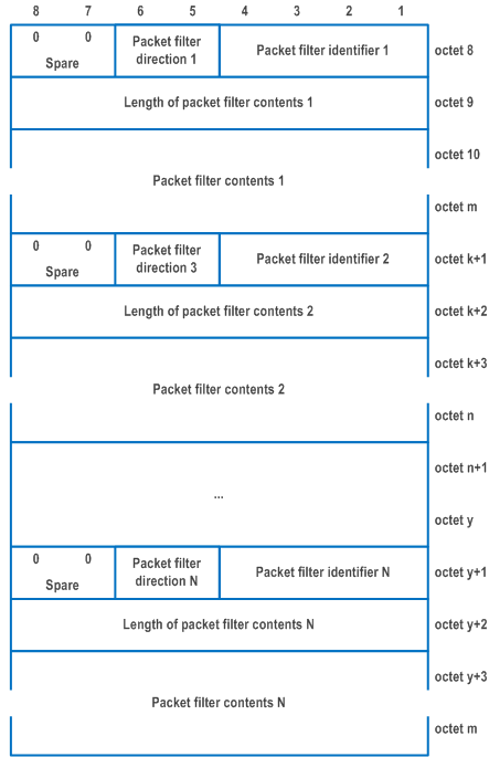
For the "create new QoS rule" operation and for the "modify existing QoS rule and replace all packet filters" operation, the packet filter list shall contain 0 or a variable number of packet filters. This number shall be derived from the coding of the number of packet filters field in octet 7.
For the "modify existing QoS rule and add packet filters" operation, the packet filter list shall contain a variable number of packet filters. This number shall be derived from the coding of the number of packet filters field in octet 7.
Each packet filter is of variable length and consists of
| |
| Bits
6 5 | |
| 0 0 | reserved |
| 0 1 | downlink only (see NOTE 2) |
| 1 0 | uplink only |
| 1 1 | bidirectional |
| The packet filter identifier field is used to identify each packet filter in a QoS rule. The least significant 4 bits are used. When the UE requests to "create new QoS rule", "modify existing QoS rule and replace all packet filters" or "modify existing QoS rule and add packet filters", the packet filter identifier values shall be set to 0. The length of the packet filter contents field contains the binary coded representation of the length of the packet filter contents field of a packet filter. The first bit in transmission order is the most significant bit. The packet filter contents field is of variable size and contains a variable number (at least one) of packet filter components. Each packet filter component shall be encoded as a sequence of a one octet packet filter component type identifier and a fixed length packet filter component value field. The packet filter component type identifier shall be transmitted first. In each packet filter, there shall not be more than one occurrence of each packet filter component type. Among the "IPv4 remote address type" and "IPv6 remote address/prefix length type" packet filter components, only one shall be present in one packet filter. Among the "IPv4 local address type" and "IPv6 local address/prefix length type" packet filter components, only one shall be present in one packet filter. Among the "single local port type" and "local port range type" packet filter components, only one shall be present in one packet filter. Among the "single remote port type" and "remote port range type" packet filter components, only one shall be present in one packet filter. Among the "destination MAC address type" and "destination MAC address range type" packet filter components, only one shall be present in one packet filter. Among the "source MAC address type" and "source MAC address range type" packet filter components, only one shall be present in one packet filter. If the "match-all type" packet filter component is present in the packet filter, no other packet filter component shall be present in the packet filter and the length of the packet filter contents field shall be set to one. If the "Ethertype type" packet filter component is present in the packet filter and the "Ethertype type" packet filter component value is neither "0800H" (for IPv4) nor "86DDH" (for IPv6), no IP packet filter component shall be present in the packet filter. The term "IP packet filter component" refers to "IPv4 remote address type", "IPv4 local address type", "IPv6 remote address/prefix length type", "IPv6 local address/prefix length type", "Protocol identifier/Next header type", "Single local port type", "Local port range type", "Single remote port type", "Remote port range type", "Security parameter index type", "Type of service/Traffic class type" and "Flow label type". The term local refers to the UE and the term remote refers to an external network entity. | |
| Packet filter component type identifier | |
| Bits
8 7 6 5 4 3 2 1 | |
| 0 0 0 0 0 0 0 1 | Match-all type (see NOTE 2) |
| 0 0 0 1 0 0 0 0 | IPv4 remote address type |
| 0 0 0 1 0 0 0 1 | IPv4 local address type |
| 0 0 1 0 0 0 0 1 | IPv6 remote address/prefix length type |
| 0 0 1 0 0 0 1 1 | IPv6 local address/prefix length type |
| 0 0 1 1 0 0 0 0 | Protocol identifier/Next header type |
| 0 1 0 0 0 0 0 0 | Single local port type |
| 0 1 0 0 0 0 0 1 | Local port range type |
| 0 1 0 1 0 0 0 0 | Single remote port type |
| 0 1 0 1 0 0 0 1 | Remote port range type |
| 0 1 1 0 0 0 0 0 | Security parameter index type |
| 0 1 1 1 0 0 0 0 | Type of service/Traffic class type |
| 1 0 0 0 0 0 0 0 | Flow label type |
| 1 0 0 0 0 0 0 1 | Destination MAC address type |
| 1 0 0 0 0 0 1 0 | Source MAC address type |
| 1 0 0 0 0 0 1 1 | 802.1Q C-TAG VID type |
| 1 0 0 0 0 1 0 0 | 802.1Q S-TAG VID type |
| 1 0 0 0 0 1 0 1 | 802.1Q C-TAG PCP/DEI type |
| 1 0 0 0 0 1 1 0 | 802.1Q S-TAG PCP/DEI type |
| 1 0 0 0 0 1 1 1 | Ethertype type |
| 1 0 0 0 1 0 0 0 | Destination MAC address range type |
| 1 0 0 0 1 0 0 1 | Source MAC address range type |
| All other values are reserved. The description and valid combinations of packet filter component type identifiers in a packet filter are defined in TS 23.501. For "match-all type", the packet filter component shall not include the packet filter component value field. For "IPv4 remote address type", the packet filter component value field shall be encoded as a sequence of a four octet IPv4 address field and a four octet IPv4 address mask field. The IPv4 address field shall be transmitted first. For "IPv4 local address type", the packet filter component value field shall be encoded as defined for "IPv4 remote address type". For "IPv6 remote address/prefix length type", the packet filter component value field shall be encoded as a sequence of a sixteen octet IPv6 address field and one octet prefix length field. The IPv6 address field shall be transmitted first. For "IPv6 local address/prefix length type", the packet filter component value field shall be encoded as defined for "IPv6 remote address /prefix length". For "protocol identifier/Next header type", the packet filter component value field shall be encoded as one octet which specifies the IPv4 protocol identifier or Ipv6 next header. For "single local port type" and "single remote port type", the packet filter component value field shall be encoded as two octets which specify a port number. For "local port range type" and "remote port range type", the packet filter component value field shall be encoded as a sequence of a two octet port range low limit field and a two octet port range high limit field. The port range low limit field shall be transmitted first. For "security parameter index", the packet filter component value field shall be encoded as four octets which specify the IPSec security parameter index. For "type of service/traffic class type", the packet filter component value field shall be encoded as a sequence of a one octet type-of-service/traffic class field and a one octet type-of-service/traffic class mask field. The type-of-service/traffic class field shall be transmitted first. For "flow label type", the packet filter component value field shall be encoded as three octets which specify the IPv6 flow label. The bits 8 through 5 of the first octet shall be spare whereas the remaining 20 bits shall contain the IPv6 flow label. For "destination MAC address type" and "source MAC address type", the packet filter component value field shall be encoded as 6 octets which specify a MAC address. When the packet filter direction field indicates "bidirectional", the destination MAC address is the remote MAC address and the source MAC address is the local MAC address. For "802.1Q C-TAG VID type", the packet filter component value field shall be encoded as two octets which specify the VID of the customer-VLAN tag (C-TAG). The bits 8 through 5 of the first octet shall be spare whereas the remaining 12 bits shall contain the VID. If there are more than one C-TAG in the Ethernet frame header, the outermost C-TAG is evaluated. For "802.1Q S-TAG VID type", the packet filter component value field shall be encoded as two octets which specify the VID of the service-VLAN tag (S-TAG). The bits 8 through 5 of the first octet shall be spare whereas the remaining 12 bits shall contain the VID. If there are more than one S-TAG in the Ethernet frame header, the outermost S-TAG is evaluated. For "802.1Q C-TAG PCP/DEI type", the packet filter component value field shall be encoded as one octet which specifies the 802.1Q C-TAG PCP and DEI. The bits 8 through 5 of the octet shall be spare, the bits 4 through 2 contain the PCP and bit 1 contains the DEI. If there are more than one C-TAG in the Ethernet frame header, the outermost C-TAG is evaluated. For "802.1Q S-TAG PCP/DEI type", the packet filter component value field shall be encoded as one octet which specifies the 802.1Q S-TAG PCP. The bits 8 through 5 of the octet shall be spare, the bits 4 through 2 contain the PCP and bit 1 contains the DEI. If there are more than one S-TAG in the Ethernet frame header, the outermost S-TAG is evaluated. For "ethertype type", the packet filter component value field shall be encoded as two octets which specify an ethertype. For "destination MAC address range type", the packet filter component value field shall be encoded as a sequence of a 6 octet destination MAC address range low limit field and a 6 octet destination MAC address range high limit field. The destination MAC address range low limit field shall be transmitted first. When the packet filter direction field indicates "bidirectional", the destination MAC address range is the remote MAC address range. For "source MAC address range type", the packet filter component value field shall be encoded as a sequence of a 6 octet source MAC address range low limit field and a 6 octet source MAC address range high limit field. The source MAC address range low limit field shall be transmitted first. When the packet filter direction field indicates "bidirectional", the source MAC address is the local MAC address range. | |
|
NOTE 1:
Octet m+2 shall not be included without octet m+1.
NOTE 2:
The "Match-all type" packet filter component type identifier shall not be used with packet filter direction "downlink only".
|
|
9.11.4.14 Session-AMBR p. 1033
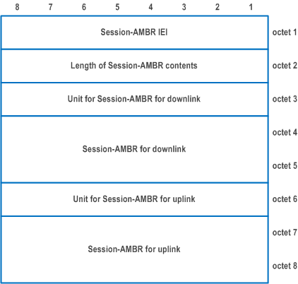
The purpose of the Session-AMBR information element is to indicate the initial subscribed PDU session aggregate maximum bit rate when the UE establishes a PDU session or to indicate the new subscribed PDU session aggregate maximum bit rate if it is changed by the network.
The Session-AMBR information element is coded as shown in Figure 9.11.4.14.1 and Table 9.11.4.14.1.
The Session-AMBR is a type 4 information element with a length of 8 octets.
| Unit for Session-AMBR for downlink (octet 3) | |
| Bits
8 7 6 5 4 3 2 1 | |
| 0 0 0 0 0 0 0 0 | value is not used (see NOTE) |
| 0 0 0 0 0 0 0 1 | value is incremented in multiples of 1 Kbps |
| 0 0 0 0 0 0 1 0 | value is incremented in multiples of 4 Kbps |
| 0 0 0 0 0 0 1 1 | value is incremented in multiples of 16 Kbps |
| 0 0 0 0 0 1 0 0 | value is incremented in multiples of 64 Kbps |
| 0 0 0 0 0 1 0 1 | value is incremented in multiples of 256 kbps |
| 0 0 0 0 0 1 1 0 | value is incremented in multiples of 1 Mbps |
| 0 0 0 0 0 1 1 1 | value is incremented in multiples of 4 Mbps |
| 0 0 0 0 1 0 0 0 | value is incremented in multiples of 16 Mbps |
| 0 0 0 0 1 0 0 1 | value is incremented in multiples of 64 Mbps |
| 0 0 0 0 1 0 1 0 | value is incremented in multiples of 256 Mbps |
| 0 0 0 0 1 0 1 1 | value is incremented in multiples of 1 Gbps |
| 0 0 0 0 1 1 0 0 | value is incremented in multiples of 4 Gbps |
| 0 0 0 0 1 1 0 1 | value is incremented in multiples of 16 Gbps |
| 0 0 0 0 1 1 1 0 | value is incremented in multiples of 64 Gbps |
| 0 0 0 0 1 1 1 1 | value is incremented in multiples of 256 Gbps |
| 0 0 0 1 0 0 0 0 | value is incremented in multiples of 1 Tbps |
| 0 0 0 1 0 0 0 1 | value is incremented in multiples of 4 Tbps |
| 0 0 0 1 0 0 1 0 | value is incremented in multiples of 16 Tbps |
| 0 0 0 1 0 0 1 1 | value is incremented in multiples of 64 Tbps |
| 0 0 0 1 0 1 0 0 | value is incremented in multiples of 256 Tbps |
| 0 0 0 1 0 1 0 1 | value is incremented in multiples of 1 Pbps |
| 0 0 0 1 0 1 1 0 | value is incremented in multiples of 4 Pbps |
| 0 0 0 1 0 1 1 1 | value is incremented in multiples of 16 Pbps |
| 0 0 0 1 1 0 0 0 | value is incremented in multiples of 64 Pbps |
| 0 0 0 1 1 0 0 1 | value is incremented in multiples of 256 Pbps |
| Other values shall be interpreted as multiples of 256 Pbps in this version of the protocol. | |
| Session-AMBR for downlink (octets 4 and 5) | |
| Octets 4 and 5 represent the binary coded value of PDU session aggregated maximum bit rate for downlink in units defined by octet 3. | |
| Unit for Session-AMBR for uplink (octet 6) | |
| The coding is identical to the unit coding defined for Session-AMBR for downlink (octet 3) | |
| Session-AMBR for uplink (octets 7 and 8) | |
| Octets 7 and 8 represent the binary coded value of PDU session aggregated maximum bit rate for uplink in units defined by octet 6. | |
|
NOTE:
In this release of the specifications if received it shall be interpreted as value is incremented in multiples of 1 Kbps. In earlier releases of specifications, the interpretation of this value is up to implementation.
|
|
9.11.4.15 SM PDU DN request container p. 1034
The purpose of the SM PDU DN request container information element is to carry a DN-specific identity of the UE in the network access identifier (NAI) format.
The SM PDU DN request container information element is coded as shown in Figure 9.11.4.15.1 and Table 9.11.4.15.1.
The SM PDU DN request container is a type 4 information element with minimal length of 3 octets and maximum length of 255 octets.
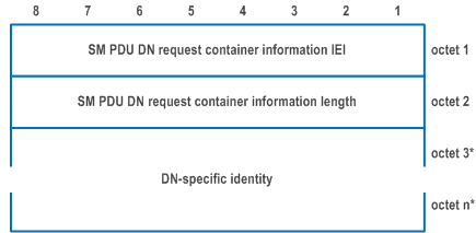
| DN-specific identity (octet 3 to octet n) | |
| A DN-specific identity of the UE in the network access identifier (NAI) format according to RFC 7542, encoded as UTF-8 string. | |