Content for TS 24.501 Word version: 18.7.0
1…
3…
4…
4.4…
4.4.3…
4.5…
4.5.3…
4.6…
4.7…
4.9…
4.15…
5…
5.2…
5.3…
5.3.2…
5.3.7…
5.3.19…
5.4…
5.4.1.3…
5.4.2…
5.4.4…
5.4.5…
5.4.6…
5.5…
5.5.1.2.4
5.5.1.2.5…
5.5.1.3…
5.5.1.3.4
5.5.1.3.5…
5.5.2…
5.6…
5.6.2…
6…
6.1.4…
6.2…
6.3…
6.3.2…
6.3.3…
6.4…
6.4.1.4…
6.4.2…
6.5…
7…
8…
8.2.9…
8.3…
9…
9.11.2…
9.11.2.10…
9.11.3…
9.11.3.4…
9.11.3.8…
9.11.3.14…
9.11.3.18C…
9.11.3.29…
9.11.3.33…
9.11.3.39…
9.11.3.45…
9.11.3.50…
9.11.3.53A…
9.11.3.68…
9.11.3.75…
9.11.4…
9.11.4.10…
9.11.4.13…
9.11.4.16…
9.11.4.30…
9.12
10…
A…
B…
C…
D…
D.6…
D.6.3…
D.6.8
D.7…
9.11.3.4 5GS mobile identity
9.11.3.5 5GS network feature support
9.11.3.6 5GS registration result
9.11.3.7 5GS registration type
...
...
9.11.3.4 5GS mobile identity p. 866
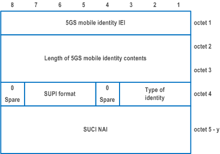
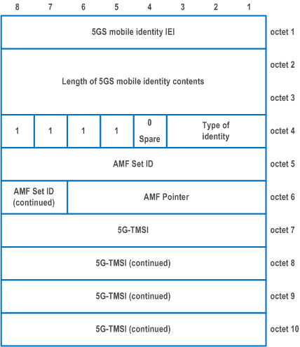
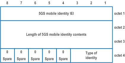
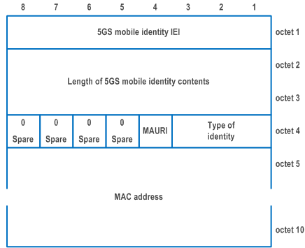
The purpose of the 5GS mobile identity information element is to provide either the SUCI, the 5G-GUTI, the IMEI, the IMEISV, the 5G-S-TMSI, the MAC address or the EUI-64.
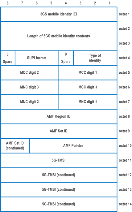
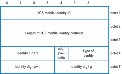
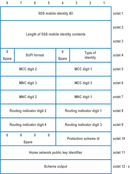
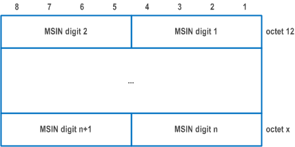
The 5GS mobile identity information element is coded as shown in Figure 9.11.3.4.1, Figure 9.11.3.4.2, Figure 9.11.3.4.3, Figure 9.11.3.4.4, Figure 9.11.3.4.5, Figure 9.11.3.4.6, Figure 9.11.3.4.7 and Figure 9.11.3.4.8, and Table 9.11.3.4.1.
The 5GS mobile identity is a type 6 information element with a minimum length of 4.
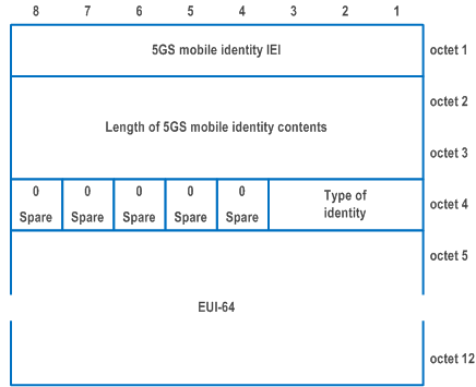
| Type of identity (octet 4) | |
| Bits
3 2 1 | |
| 0 0 0 | No identity (see NOTE 1) |
| 0 0 1 | SUCI |
| 0 1 0 | 5G-GUTI |
| 0 1 1 | IMEI |
| 1 0 0 | 5G-S-TMSI |
| 1 0 1 | IMEISV |
| 1 1 0 | MAC address |
| 1 1 1 | EUI-64 |
| All other values are reserved. | |
| Odd/even indication (octet 4) | |
| Bit
4 | |
| 0 | even number of identity digits |
| 1 | odd number of identity digits |
| For the 5G-GUTI, then bits 5 to 8 of octet 4 are coded as "1111", octet 5 through 7 contain the MCC and MNC values as specified below, octet 8 through 10 contain the AMF Region ID, the AMF Set ID and the AMF Pointer values and octet 11 through 14 contain the 5G-TMSI as defined in TS 23.003. | |
| MCC, Mobile country code (octet 5, octet 6 bits 1 to 4) | |
| The MCC field is coded as in ITU-T Recommendation E.212 [42], Annex A. | |
| MNC, Mobile network code (octet 6 bits 5 to 8, octet 7) | |
| The coding of this field is the responsibility of each administration but BCD coding shall be used. The MNC shall consist of 2 or 3 digits. If a network operator decides to use only two digits in the MNC, bits 5 to 8 of octet 6 shall be coded as "1111". The MCC and MNC digits are coded as octets 6 to 8 of the Temporary mobile group identity IE in Figure 10.5.154 of TS 24.008. | |
| AMF Region ID (octet 8) | |
| This field contains the binary encoding of the AMF Region ID. Bit 8 of octet 7 is the most significant bit and bit 1 of octet 7 is the least significant bit. | |
| AMF Set ID (octet 9, octet 10 bits 7 to 8) | |
| This field contains the binary encoding of the AMF Set ID. Bit 8 of octet 9 is the most significant bit and bit 7 of octet 10 is the least significant bit. | |
| AMF Pointer (octet 10 bits 1 to 6) | |
| This field contains the binary encoding of the AMF Pointer. Bit 6 of octet 9 is the most significant bit and bit 1 of octet 9 is the least significant bit. | |
| 5G-TMSI (octet 11 to 14) | |
| Bit 8 of octet 11 is the most significant bit and bit 1 of octet 14 is the least significant bit. | |
| Identity digit (octet 4 bits 5 to 8, octet 5 etc.) | |
| For the IMEI, Identity digit field is coded using BCD coding. If the number of identity digits is even then bits 5 to 8 of the last octet shall be filled with an end mark coded as "1111". The format of the IMEI is described in TS 23.003. For the IMEISV, Identity digit field is coded using BCD coding. Bits 5 to 8 of the last octet shall be filled with an end mark coded as "1111". The format of the IMEISV is described in TS 23.003. For the SUCI, bit 8 of octet 4 is spare and shall be coded as zero. Bits 5-7 of octet 4 contain the SUPI format and are coded as shown below. | |
| SUPI format (octet 4, bits 5-7) | |
| Bits
7 6 5 | |
| 0 0 0 | IMSI |
| 0 0 1 | Network specific identifier |
| 0 1 0 | GCI |
| 0 1 1 | GLI |
| All other values are interpreted as IMSI by this version of the protocol. For the SUCI with SUPI format "IMSI", octets 5 through 7 contain the MCC and MNC values as specified below. For subsequent fields, bit 8 of octet 8 is the most significant bit and bit 1 of the last octet the least significant bit. The required fields for the SUCI are as defined in TS 23.003. | |
| MCC, Mobile country code (octet 5, octet 6 bits 1 to 4) | |
| The MCC field is coded as in ITU-T Recommendation E.212 [42], Annex A. | |
| MNC, Mobile network code (octet 6 bits 5 to 8, octet 7) | |
| The coding of this field is the responsibility of each administration but BCD coding shall be used. The MNC shall consist of 2 or 3 digits. If a network operator decides to use only two digits in the MNC, bits 5 to 8 of octet 6 shall be coded as "1111". The MCC and MNC digits are coded as octets 6 to 8 of the Temporary mobile group identity IE in Figure 10.5.154 of TS 24.008. | |
| Routing indicator (octets 8-9) | |
| Routing Indicator shall consist of 1 to 4 digits. The coding of this field is the responsibility of home network operator but BCD coding shall be used. If a network operator decides to assign less than 4 digits to Routing Indicator, the remaining digits shall be coded as "1111" to fill the 4 digits coding of Routing Indicator (see NOTE 2). If no Routing Indicator is configured in the USIM or the ME, the UE shall code bits 1 to 4 of octet 8 of the Routing Indicator as "0000" and the remaining digits as "1111". | |
| Protection scheme identifier (octet 10 bits 1 to 4) | |
| Bits
4 3 2 1 | |
| 0 0 0 0 | Null scheme |
| 0 0 0 1 | ECIES scheme profile A |
| 0 0 1 0 | ECIES scheme profile B |
| 0 0 1 1 - 1 0 1 1 | Reserved |
| 1 1 0 0 - 1 1 1 1 | Operator-specific protection scheme |
| Bits 5-8 of octet 10 are spare and shall be coded as zero. | |
| Home network public key identifier (octet 11) | |
| The Home network public key identifier (PKI) field is coded as defined in TS 23.003. Home network public key identifier shall be coded as "00000000" when Protection scheme identifier is set to "0000" (i.e. Null scheme). | |
| Bits
8 7 6 5 4 3 2 1 | |
| 0 0 0 0 0 0 0 0 | Home network PKI value 0 |
| 0 0 0 0 0 0 0 1 - | Home network PKI value (1-254) |
| 1 1 1 1 1 1 1 0 | |
| 1 1 1 1 1 1 1 1 | Reserved |
| Scheme output (octets 12 to x) | |
| The Scheme output field consists of a string of characters with a variable length or hexadecimal digits as specified in TS 23.003. If Protection scheme identifier is set to "0000" (i.e. Null scheme), then the Scheme output consists of the MSIN and is coded using BCD coding with each digit of the MSIN coded over 4 bits. If the MSIN includes an odd number of digits, bits 5 to 8 of octet x shall be coded as "1111". If Protection scheme identifier is not "0000" (i.e. ECIES scheme profile A, ECIES scheme profile B or Operator-specific protection scheme), then Scheme output is coded as hexadecimal digits. For the SUCI with SUPI format set to "Network specific identifier", the SUCI NAI field contains an NAI constructed as specified in subclause 28.7.3 of TS 23.003 and encoded as UTF-8 string. For the SUCI with SUPI format set to "GCI", the SUCI NAI field contains an NAI constructed as specified in subclause 28.15.5 of TS 23.003 and encoded as UTF-8 string. For the SUCI with SUPI format set to "GLI", the SUCI NAI field contains an NAI constructed as specified in subclause 28.16.5 of TS 23.003 and encoded as UTF-8 string. For the 5G-S-TMSI, bits 5 to 8 of octet 4 are coded as "1111". The coding of the 5G-S-TMSI is left open for each administration. | |
| AMF Set ID (octet 5, octet 6 bits 7 to 8) | |
| This field contains the binary encoding of the AMF Set ID. Bit 8 of octet 5 is the most significant bit and bit 7 of octet 6 is the least significant bit. | |
| AMF Pointer (octet 6 bits 1 to 6) | |
| This field contains the binary encoding of the AMF Pointer. Bit 6 of octet 6 is the most significant bit and bit 1 of octet 6 is the least significant bit. | |
| 5G-TMSI (octet 7 to 10) | |
| Bit 8 of octet 7 is the most significant bit and bit 1 of octet 10 is the least significant bit. For Type of identity "No identity", the length of mobile identity contents parameter shall be set to 1 and the bits 4-8 of octet 4 are spare and shall be coded as zero. | |
| MAC address usage restriction indication (MAURI) (octet 4 bit 4) | |
| Bit
4 | |
| 0 | No restrictions |
| 1 | MAC address is not usable as an equipment identifier |
| MAC address (octets 5 to 10) | |
| This field contains the MAC address as defined in subclause 8 of IEEE Std 802 [43]. Bit 8 of octet 5 is the most significant bit and bit 1 of octet 10 is the least significant bit. | |
| EUI-64 (octets 5 to 12) | |
| This field contains an EUI-64 as defined in [48]. Bit 8 of octet 5 is the most significant bit and bit 1 of octet 12 is the least significant bit. | |
|
NOTE 1:
This can be used when the requested identity is not available at the UE during the identification procedure.
NOTE 2:
For a 3-digit Routing Indicator, e.g "567", bits 1 to 4 of octet 8 are coded as "0101", bits 5 to 8 of octet 8 are coded as "0110", bits 1 to 4 of octet 9 are coded as "0111", bits 5 to 8 of octet 9 are coded as "1111".
|
|
9.11.3.5 5GS network feature support p. 872
The purpose of the 5GS network feature support information element is to indicate whether certain features are supported by the network.
The 5GS network feature support information element is coded as shown in Figure 9.11.3.5.1 and Table 9.11.3.5.1.
The 5GS network feature support is a type 4 information element with a minimum length of 3 octets and a maximum length of 6 octets.
If:
- the length of 5GS network feature support contents field is set to one, then the UE shall interpret this as a receipt of an information element with all bits of octet 4, octet 5 and octet 6 coded as zero.
- the length of 5GS network feature support contents field is set to two, the UE shall interpret this as a receipt of an information element with all bits of octet 5 and octet 6 coded as zero.
- the length of 5GS network feature support contents field is set to three, the UE shall interpret this as a receipt of an information element with all bits of octet 6 coded as zero.
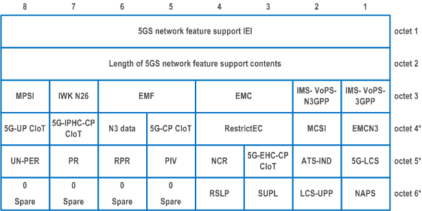
| IMS voice over PS session over 3GPP access indicator (IMS-VoPS-3GPP) (octet 3, bit 1) | |
| This bit indicates the support of IMS voice over PS session over 3GPP access (see NOTE 1). | |
| 0 | IMS voice over PS session not supported over 3GPP access |
| 1 | IMS voice over PS session supported over 3GPP access |
| IMS voice over PS session over non-3GPP access indicator (IMS-VoPS-N3GPP) (octet 3, bit 2) | |
| This bit indicates the support of IMS voice over PS session over non-3GPP access. | |
| 0 | IMS voice over PS session not supported over non-3GPP access |
| 1 | IMS voice over PS session supported over non-3GPP access |
| Emergency service support indicator for 3GPP access (EMC) (octet 3, bit 3 and bit 4) | |
| These bits indicate the support of emergency services in 5GS for 3GPP access (see NOTE 1). | |
| Bits
4 3 | |
| 0 0 | Emergency services not supported |
| 0 1 | Emergency services supported in NR connected to 5GCN only |
| 1 0 | Emergency services supported in E-UTRA connected to 5GCN only |
| 1 1 | Emergency services supported in NR connected to 5GCN and E-UTRA connected to 5GCN |
| Emergency services fallback indicator for 3GPP access (EMF) (octet 3, bit 5 and bit 6) | |
| These bits indicate the support of emergency services fallback for 3GPP access (see NOTE 1). | |
| Bits
6 5 | |
| 0 0 | Emergency services fallback not supported |
| 0 1 | Emergency services fallback supported in NR connected to 5GCN only |
| 1 0 | Emergency services fallback supported in E-UTRA connected to 5GCN only |
| 1 1 | Emergency services fallback supported in NR connected to 5GCN and E-UTRA connected to 5GCN |
| Interworking without N26 interface indicator (IWK N26) (octet 3, bit 7) | |
| This bit indicates whether interworking without N26 interface is supported. | |
| 0 | Interworking without N26 interface not supported |
| 1 | Interworking without N26 interface supported |
| MPS indicator (MPSI) (octet 3, bit 8) | |
| This bit indicates the validity of MPS. | |
| 0 | Access identity 1 not valid |
| 1 | Access identity 1 valid |
| Emergency service support for non-3GPP access indicator (EMCN3) (octet 4, bit 1) | |
| This bit indicates the support of emergency services in 5GS for non-3GPP access. | |
| Bit (see NOTE 2)
1 | |
| 0 | Emergency services not supported over non-3GPP access |
| 1 | Emergency services supported over non-3GPP access |
| MCS indicator (MCSI) (octet 4, bit 2) | |
| This bit indicates the validity of MCS. | |
| 0 | Access identity 2 not valid |
| 1 | Access identity 2 valid |
| Restriction on enhanced coverage (RestrictEC) (octet 4, bit 3 and bit 4) | |
| These bits indicate enhanced coverage restricted information. In WB-N1 mode these bits are set as follows: | |
| Bits
4 3 | |
| 0 0 | Both CE mode A and CE mode B are not restricted |
| 0 1 | Both CE mode A and CE mode B are restricted |
| 1 0 | CE mode B is restricted |
| 1 1 | Reserved |
| In NB-N1 mode these bits are set as follows | |
| Bits
4 3 | |
| 0 0 | Use of enhanced coverage is not restricted |
| 0 1 | Use of enhanced coverage is restricted |
| 1 0 | Reserved |
| 1 1 | Reserved |
| Control plane CIoT 5GS optimization (5G-CP CIoT) (octet 4, bit 5) | |
| This bit indicates the capability for control plane CIoT 5GS optimization. | |
| 0 | Control plane CIoT 5GS optimization not supported |
| 1 | Control plane CIoT 5GS optimization supported |
| N3 data transfer (N3 data) (octet 4, bit 6) | |
| This bit indicates the capability for N3 data transfer. | |
| 0 | N3 data transfer supported |
| 1 | N3 data transfer not supported |
| IP header compression for control plane CIoT 5GS optimization (5G-IPHC-CP CIoT) (octet 4, bit 7) | |
| This bit indicates the capability for IP header compression for control plane CIoT 5GS optimization. | |
| 0 | IP header compression for control plane CIoT 5GS optimization not supported |
| 1 | IP header compression for control plane CIoT 5GS optimization supported |
| User plane CIoT 5GS optimization (5G-UP CIoT) (octet 4, bit 8) | |
| This bit indicates the capability for user plane CIoT 5GS optimization. | |
| 0 | User plane CIoT 5GS optimization not supported |
| 1 | User plane CIoT 5GS optimization supported |
| Location Services indicator in 5GC (5G-LCS) (octet 5, bit 1) | |
| 0 | Location services via 5GC not supported |
| 1 | Location services via 5GC supported |
| ATSSS support indicator (ATS-IND) (octet 5, bit 2) | |
| This bit indicates the network support for ATSSS. | |
| 0 | ATSSS not supported |
| 1 | ATSSS supported |
| Ethernet header compression for control plane CIoT 5GS optimization (5G-EHC-CP CIoT) (octet 5, bit 3) | |
| This bit indicates the capability for Ethernet header compression for control plane CIoT 5GS optimization | |
| 0 | Ethernet header compression for control plane CIoT 5GS optimization not supported |
| 1 | Ethernet header compression for control plane CIoT 5GS optimization supported |
| N1 NAS signalling connection release (NCR) (octet 5, bit 4) | |
| This bit indicates whether N1 NAS signalling connection release is supported. | |
| 0 | N1-NAS signalling connection release not supported |
| 1 | N1-NAS signalling connection release supported |
| Paging indication for voice services (PIV) (octet 5, bit 5) | |
| This bit indicates whether paging indication for voice services is supported. | |
| 0 | paging indication for voice services not supported |
| 1 | paging indication for voice services supported |
| Reject paging request (RPR) (octet 5, bit 6) | |
| This bit indicates whether reject paging request is supported. | |
| 0 | reject paging request not supported |
| 1 | reject paging request supported |
| Paging restriction (PR) (octet 5, bit 7) | |
| This bit indicates whether paging restriction is supported. | |
| 0 | paging restriction not supported |
| 1 | paging restriction supported |
| UN-PER (octet 5, bit 8) | |
| This bit indicates the capability to support Unavailability period | |
| 0 | unavailability period not supported |
| 1 | unavailability period supported |
| Non-3GPP access path switching (NAPS) (octet 6, bit 1) | |
| This bit indicates whether non-3GPP access path switching is supported. | |
| 0 | non-3GPP access path switching not supported |
| 1 | non-3GPP access path switching supported |
| LCS-UPP user plane positioning (LCS-UPP) (octet 6, bit 2) | |
| This bit indicates the capability to support LCS-UPP user plane positioning (see TS 23.273). | |
| 0 | User plane positioning using LCS-UPP not supported |
| 1 | User plane positioning using LCS-UPP supported |
| SUPL user plane positioning (SUPL) (octet 6, bit 3) | |
| This bit indicates the capability to support SUPL user plane positioning (see TS 38.305 and TS 23.271). | |
| 0 | User plane positioning using SUPL not supported |
| 1 | User plane positioning using SUPL supported |
| Ranging and sidelink positioning support (RSLP) (octet 6, bit 4) | |
| This bit indicates the capability to support ranging and sidelink positioning. | |
| 0 | Ranging and sidelink positioning not supported |
| 1 | Ranging and sidelink positioning supported |
| Bits 5 to 8 of octet 6 are spare and shall be coded as zero. | |
|
NOTE 1:
For a registration procedure over non-3GPP access, bit 1 of octet 3 and bits 3 to 7 of octet 3 are ignored.
NOTE 2:
For a registration procedure over 3GPP access, bit 2 of octet 3 and bit 1 of octet 4 are ignored.
|
|
9.11.3.6 5GS registration result p. 878
The purpose of the 5GS registration result information element is to specify the result of a registration procedure.
The 5GS registration result information element is coded as shown in Figure 9.11.3.6.1 and Table 9.11.3.6.1.
The 5GS registration result is a type 4 information element with a length of 3 octets.

| 5GS registration result value (octet 3, bits 1 to 3) (NOTE) | |
| Bits
3 2 1 | |
| 0 0 1 | 3GPP access |
| 0 1 0 | Non-3GPP access |
| 0 1 1 | 3GPP access and non-3GPP access |
| 1 1 1 | reserved |
| All other values are unused and shall be treated as "3GPP access", if received by the UE. | |
| SMS over NAS transport allowed (SMS allowed) (octet 3, bit 4) (NOTE) | |
| 0 | SMS over NAS not allowed |
| 1 | SMS over NAS allowed |
| Network slice-specific authentication and authorization is to be performed (NSSAA to be performed) (octet 3, bit 5) (NOTE) | |
| 0 | Network slice-specific authentication and authorization is not to be performed |
| 1 | Network slice-specific authentication and authorization is to be performed |
| Emergency registered (octet 3, bit 6) (NOTE) | |
| 0 | Not registered for emergency services |
| 1 | Registered for emergency services |
| Disaster roaming registration result value (octet 3, bit 7) | |
| 0 | No additional information |
| 1 | Request for registration for disaster roaming service accepted as registration not for disaster roaming service |
| Bit 8 of octet 3 is spare and shall be coded as zero. | |
|
NOTE:
All bits other than bit 6 in octet 3 shall be ignored by the UE when the 5GS registration result IE is received in the CONFIGURATION UPDATE COMMAND message.
|
|
9.11.3.7 5GS registration type p. 879
The purpose of the 5GS registration type information element is to indicate the type of the requested registration.
The 5GS registration type information element is coded as shown in Figure 9.11.3.7.1 and Table 9.11.3.7.1.
The 5GS registration type is a type 1 information element with a length of 1 octet.

| 5GS registration type value (octet 1, bits 1 to 3) | |
| Bits
3 2 1 | |
| 0 0 1 | initial registration |
| 0 1 0 | mobility registration updating |
| 0 1 1 | periodic registration updating |
| 1 0 0 | emergency registration |
| 1 0 1 | SNPN onboarding registration |
| 1 1 0 | disaster roaming mobility registration updating |
| 1 1 1 | disaster roaming initial registration |
| All other values are unused and shall be interpreted as "initial registration", if received by the network. | |
| Follow-on request bit (FOR) (octet 1, bit 4) | |
| 0 | No follow-on request pending |
| 1 | Follow-on request pending |