Content for TS 23.434 Word version: 19.2.0
0…
4…
5
6…
6.4…
6.5…
6.5.3…
7…
8…
8.2.2…
9…
9.3…
9.3.2.21…
9.3.3…
9.3.6…
9.3.11…
9.3.13…
9.3.14…
9.4…
9.4.6…
9.5…
10…
10.3…
10.3.2.22…
10.3.3…
10.3.7…
10.3.10…
10.4…
11…
11.3…
11.3.3…
11.4…
12…
12.3…
13…
14…
14.2.2.2…
14.3…
14.3.2.20…
14.3.2.40…
14.3.3…
14.3.3.3…
14.3.4…
14.3.4.6
14.3.4.7…
14.3.4A…
14.3.4A.3…
14.3.4A.4…
14.3.4A.6…
14.3.4A.8…
14.3.4A.9…
14.3.4A.10…
14.3.5…
14.3.6…
14.3.9…
14.3.12…
14.4…
15…
16…
17…
18…
A
B…
14.3.12 UE unified traffic pattern and monitoring management
14.3.12.1 General
14.3.12.2 UE unified traffic pattern and monitoring management subscription procedure
14.3.12.3 UE unified traffic pattern update notification procedure
14.3.12.4 Management and 5GC exposure procedures
14.3.12.4.1 General
14.3.12.4.2 UE unified traffic pattern management procedure
14.3.12.4.3 Network parameter coordination procedure
14.3.13 Background Data Transfer configuration
14.3.13.1 General
14.3.13.2 Request and Select Background Data Transfer Policy
14.3.13.3 Reselect Background Data Transfer Policy
14.3.13.4 BDT configuration get
14.3.13.5 BDT configuration update
14.3.13.6 BDT configuration delete
14.3.14.1 General
14.3.14.2 Device Triggering via NRM procedure
...
...
14.3.12 UE unified traffic pattern and monitoring management |R18| p. 261
14.3.12.1 General p. 261
UE unified traffic pattern and monitoring management procedures allow NRM to offer services leveraging CN exposure APIs for network parameter values configuration and UE monitoring event management.
14.3.12.2 UE unified traffic pattern and monitoring management subscription procedure |R19| p. 261
VAL servers can indicate to the NRM server interest in receiving UE unified traffic patterns and monitoring management services by sending the UE unified traffic pattern and monitoring management subscription requests.
The subscription requests from each VAL server also include the traffic pattern configuration of the requester, which refers to application-level patterns of data traffic. The NRM server aggregates the traffic patterns obtained from the requestors (and described in Table 14.3.2.53-2) to determine the UE unified traffic patterns per UE. The UE unified traffic patterns are described via Table 14.3.2.55-1 for the UE unified traffic pattern update notification. These aggregated traffic patterns per UE (termed UE unified traffic pattern) are updated/adjusted by the NRM Server based on information obtained from UE monitoring.
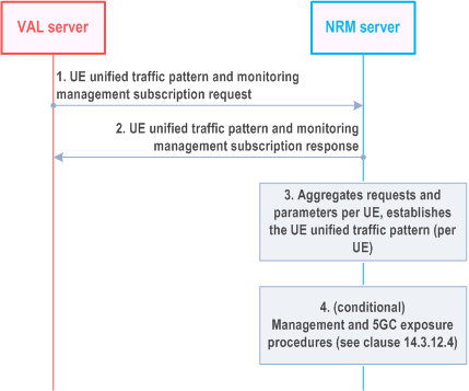
Step 1.
In order to subscribe to the NRM Server services, the VAL server sends the UE unified traffic pattern and monitoring management subscription request, as detailed in clause 14.3.2.53. The subscription request may include traffic pattern configuration, which provides the traffic patterns of the specific VAL Server. The request may also include Management subscription indications which indicate to the NRM Server which management and 5GC exposure procedures the VAL server allows the NRM Server to perform on its behalf.
Step 2.
Upon receipt of the request, the NRM server sends a UE unified traffic pattern and monitoring management subscription response as detailed in clause 14.3.2.54.
Step 3.
The NRM Server aggregates UE unified traffic pattern and monitoring management subscription requests from different VAL servers and determines the UE unified traffic pattern per UE (using the traffic patterns of all the communicating with the UE).
Step 4.
Depending on the subscription requests received and local policies, the NRM Server executes one or more management and 5GC exposure procedure (per UE). Management and 5GC exposure procedures are detailed in clause 14.3.12.4.
The NRM Server determines the management procedures required to be executed on behalf of the VAL Servers based on the received management subscription indications as follows:
- If the UE unified traffic pattern monitoring management indication is provided, the NRM Server executes steps 1-3 of the UE unified traffic pattern monitoring procedure detailed in clause 14.3.12.4.2.
- If the UE unified traffic pattern monitoring update notification indication is provided, the NRM Server executes the steps 1-4 of the UE unified traffic pattern monitoring procedure detailed in clause 14.3.12.4.2.
- If the Network parameter coordination indication is provided, the NRM executes the network parameter coordination procedure detailed in clause 14.3.12.4.3.
14.3.12.3 UE unified traffic pattern update notification procedure p. 262
An NRM Server can provide updated UE unified traffic pattern information to VAL servers by sending UE unified traffic pattern update notifications as shown in Figure 14.3.12.3-1. The UE unified traffic pattern management procedure detailed in clause 14.3.12.4.2. is an example of procedure which may result in UE unified traffic pattern updates at the NRM server, based on which UE unified traffic pattern update notifications are provided.
Pre-conditions:
- The VAL server has subscribed for UE unified traffic pattern and monitoring management services, requesting to receive UE unified traffic pattern update notifications

Step 1.
The NRM server sends the UE unified traffic pattern update notification when either of the following occurs:
- Monitoring events lead to updates in the UE unified traffic pattern (e.g., to schedule elements in Table 14.3.2.55-1) the NRM server sends a corresponding notification to the VAL server. Other notifications may be provided, e.g., if the stationary indication changes.
- An NP Configuration Notification is received with a new set of applied network parameters and if the NRM Server determines that the new configuration is incompatible with the current UE unified traffic pattern (see also clause 14.3.12.4.2 step 3).
14.3.12.4 Management and 5GC exposure procedures p. 263
14.3.12.4.1 General p. 263
The management and 5GC exposure procedures in this clause show NRM processing and its interactions with 5GC in support of the functionality described in clause 14.3.12.2.
14.3.12.4.2 UE unified traffic pattern management procedure p. 263
The UE unified traffic pattern management procedure is used to determine and manage a unified traffic pattern applicable to a specified UE. The NRM Server then uses the 5GC exposure of UE monitoring events to update the UE unified traffic pattern.
Pre-conditions:
-
The NRM Server determines to provide the service for a specific UE if either of the following conditions is true:
- It receives UE unified traffic pattern monitoring management indications in UE unified traffic pattern and monitoring management subscription requests; or
- It determines to provide Network parameter coordination services for the UE.
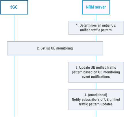
Step 1.
The NRM Server determines an initial UE unified traffic pattern, e.g. by using all Traffic pattern configurations received for the UE .
Step 2.
The NRM Server determines, based on local policy that UE monitoring events are to be configured and executes the corresponding Monitoring procedure as described in clause 4.4.2 of TS 29.122.
Step 3.
The NRM Server updates the UE unified traffic pattern based on the received monitoring events as follows:
Step 4.
- If a Monitoring Notification report for UE_REACHABILITY is received, and idleStatusInfo information is provided in the report, the NRM Server changes the schedule element of the UE unified traffic pattern such that the duration of activity is set to the value of the activeTime parameter configured in the idleStatusInfo.
- If a Monitoring Notification report for AVAILABILITY_AFTER_DDN_FAILURE is received after UEs transition to idle mode, the NRM Server updates the schedule element of the UE unified traffic pattern such that: the start of an activity window is based on the Idle Timestamp, with a periodicity equal to the TAU/RAU Timer; the duration of the activity window indicates the Active Time value.
- If a Monitoring Notification report for COMMUNICATION_FAILURE is received The NRM updates the schedule element of the UE unified traffic pattern to indicate that no communications are currently available (e.g. by using a keyword such as "NULL"). Local policies may specify events/ thresholds further defining when the NRM may provide a UE unified traffic pattern update based on monitoring events. For example, the update may be provided only after repeated communication failures are received within a timespan, or only if high reliability communications are expected. It is recommended that UE Reachability monitoring is also enabled in conjunction with the Communication Failure monitoring. This enables the NRM to provide updated timing information once the UE becomes reachable again.
- If a Monitoring Notification report for LOSS_OF_CONNECTIVITY is received, the NRM Server changes the schedule element of the UE unified traffic pattern to indicate that no communications are currently available.
Conditional: The NRM Server notifies subscribers of the UE unified traffic pattern updates, as described in clause 14.3.2.55
14.3.12.4.3 Network parameter coordination procedure p. 264
The network parameter coordination procedure uses UE unified traffic pattern information to influence aspects of UE/network behaviour such as the UE's PSM and extended idle mode DR14. For this purpose, parameter values may be suggested for Maximum Latency and Maximum Response Time for a UE. 5GC may choose to accept, reject or modify the suggested configuration parameter value.
Pre-conditions:
- The NRM Server determines to provide the service for a specific UE after receiving Network parameter coordination indications in UE unified traffic pattern and monitoring management subscription requests, subject to policy.
- The NRM Server determines and manages UE unified traffic patterns as described in clause 14.3.12.4.2.
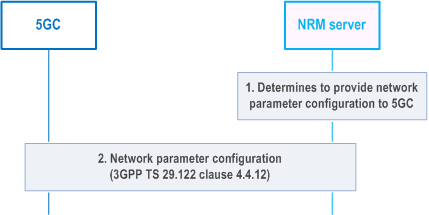
Step 1.
The NRM Server determines to provide Network parameter configuration to 5GC. This determination can be based on updates to the UE unified traffic patterns resulting from interactions with VAL Servers (e.g. Traffic pattern configuration updates), on local policies, etc.
The NRM Server determines parameters the needed for NpConfiguration data structure as specified in TS 29.122 from the UE unified traffic patterns as follows:
Step 2.
- maximumLatency - This value tells the network how long the UE is allowed to sleep. Setting it to 0 will disable PSM, extended idle mode DRX, and extended buffering. The NRM Server can extract the periodicity derived from the UE unified traffic pattern, which includes the schedule elements for the UEs communications with all VAL servers. The NRM Server sets Maximum Latency to be approximately the periodicity of the active periods derived from the schedule element of the UE unified traffic pattern.
- maximumResponseTime - When the UE uses PSM, Maximum Response Time tells the network how long the UE should stay reachable after a transition to idle. When the UE uses eDRX, Maximum Response Time is used by the network to determine when to send a reachability notification before a UE's paging occasion. The NRM Server extracts a duration of activity from the schedule element of the UE unified traffic pattern and sets Maximum Response Time to reflect the duration of activity, indicating how long the UE should stay reachable for downlink communications.
The NRM Server performs the Network Parameter Configuration procedure as described in clause 4.4.12 of TS 29.122.
14.3.13 Background Data Transfer configuration |R18| p. 265
14.3.13.1 General p. 265
The Background Data Transfer (BDT) feature requires an initial step in which BDT policies are requested and negotiated. BDT Policy requests to the 3GPP network are based on an expected time window and UE set, with additional optional information e.g., expected data volume per UE. The UE set may be indicated as an expected number of UEs, a group ID or geographical area.
The feature allows for the NRM server involved to negotiate the BDT policies proposed by the network. It also allows the NRM server to enable notifications to be sent, should network conditions affect future BDT policies.
Based on the BDT policies obtained using the procedures detailed in this clause, a VAL server can initiate a data transfer to the client at the negotiated time and with the negotiated charging rates. The data transfer between the VAL Server and the VAL Client is performed without NRM Server enablement. Service layer functionality for the purpose of facilitating the data transfer with the negotiated BDT policy is not in scope of this specification.
14.3.13.2 Request and Select Background Data Transfer Policy p. 266
Figure 14.3.13.2-1 depicts a general procedure for the request and configuration of traffic policies for BDT initiated by a request from a VAL Server.
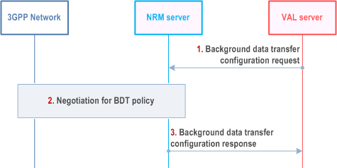
Step 1.
A VAL Server requests the NRM Server to negotiate with the 3GPP network a background data transfer policy using the BDT_Configuration_request (see clause 14.4.2.15).
The request includes expected data volume, expected number of UEs, expected time window for the background data transfer. The request may also include group ID, geographic information for the UEs, a request expiration time, guidance for policy selection. If guidance for policy selection is not included, the VAL Server indicates if the NRM Server may choose independently from among multiple transfer policies.
Step 2.
Based on the request expiration time and Service Provider policies, NRM Server may determine to delay interactions with the 3GPP network in order to negotiate on behalf of multiple VAL Servers.
The NRM Server performs the procedure for negotiation of background data transfer policy as described in clause 4.16.7.2 of TS 23.502. The procedure requires that expected data volume, expected number of UEs, and expected time window are provided by the NRM Server. If the NRM Server determines to negotiate on behalf of multiple VAL Servers, the parameters included reflects a superset of the individual VAL Server requests.
The 3GPP network determines one or more applicable BDT policies based on the requesting Background Data Transfer parameters. A list of BDT policies and a mandatory BDT Reference ID is provided to the NRM Server. Each BDT policy includes charging rating group reference and allocated time window and optional maximum UL and DL bandwidth as specified by TS 23.503. The NRM Server uses ASP policies and the transfer selection guidance (if available) to select a BDT policy. The NRM Server informs the 3GPP Network of the selected BDT policy.
Step 3.
The NRM Server stores the BDT configuration information with the information received from VAL server in step 1 along with the BDT Reference ID and selected BDT policy. The NRM server responds to the VAL Server, providing the BDT Reference ID and allocated time window of the selected background data transfer policy.
14.3.13.3 Reselect Background Data Transfer Policy p. 267
Figure 14.3.13.3-1 depicts a general procedure for reselecting BDT policies after BDT warning.
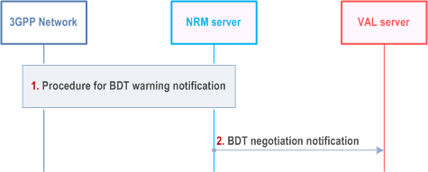
Step 1.
The 3GPP Network, via NEF, sends the BDT warning (BDT Policy negotiate) notification to the NRM server as specified in step 10, clause 4.16.7.3 of TS 23.502. The notification includes the affected BDT Reference ID and list of candidate BDT policies.
Each of the BDT policies in the candidate BDT list includes charging rating group reference and time window, as well as optional maximum UL and DL bandwidth.
The NRM Server checks the new BDT policies included in the candidate list of the BDT warning notification. The NRM Server determines whether the notification affects multiple VAL Servers or not. The NRM Server uses ASP policies and the transfer selection guidance (if available) provided with the initial VAL Server request to select a policy.
The NRM Server informs the 3GPP Network of the selected transfer policy or that no new policy has been selected by using steps 11-16 of the procedure for BDT warning notification in clause 4.16.7.3 of TS 23.502.
Step 2.
The NRM server updates the BDT configuration information with the newly selected BDT policy or no BDT policy is selected for the BDT Reference ID. The NRM Server sends a BDT_Negotiation_notification (see clause 14.4.2.16), to the VAL server, providing information about the newly selected BDT policy, or that no BDT policy is selected for the BDT Reference ID. If a new BDT policy is selected by the NRM server, the information provided to the VAL Server includes the BDT Reference ID and the granted time window.
14.3.13.4 BDT configuration get p. 267
Figure 14.3.13.4-1 illustrates a procedure for retrieving the BDT configuration on the NRM server by the VAL server.
Pre-conditions:
- The VAL server has performed the BDT configuration request as specified in clause 14.3.13.2.
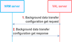
Step 1.
A VAL Server requests the NRM Server to retrieve its background data transfer policy configuration using the BDT_Configuration_Get_request (see clause 14.4.2.19).
The request includes identifier for the BDT policy configuration stored at the NRM server.
Step 2.
The NRM Server provides a response to the VAL server indicating success or failure of the operation and the BDT configuration data available at the NRM server.
14.3.13.5 BDT configuration update p. 268
Figure 14.3.13.5-1 illustrates a procedure for updating the BDT configuration on the NRM server by the VAL server.
Pre-conditions:
- The VAL server has performed the BDT configuration request as specified in clause 14.3.13.2.
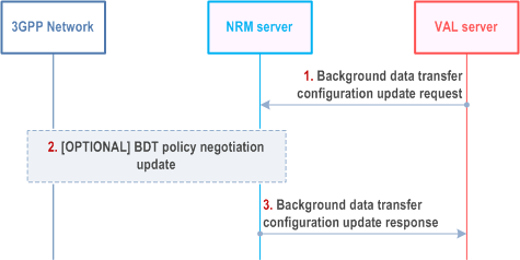
Step 1.
A VAL Server requests the NRM Server to update its background data transfer policy configuration using the BDT_Configuration_Update_request (see clause 14.4.2.20).
The request includes identifier for the BDT policy configuration stored at the NRM server and one or more updated information like expected data volume, expected number of UEs, expected time window for the background data transfer, geographic information for the UEs, a request expiration time, guidance for policy selection.
Step 2.
The NRM Server may perform the BDT policy negotiation update as specified in clause 4.16.7.2 of TS 23.502. The request for update of the BDT policy configuration by the VAL server may provide several updates to the requirements of the VAL server to perform BDT to the VAL UE or group of VAL UEs. This may impact the selected BDT policy.
Step 3.
The NRM Server provides a response to the VAL server indicating success or failure of the operation.
14.3.13.6 BDT configuration delete p. 269
Figure 14.3.13.6-1 illustrates a procedure for deleting the BDT configuration on the NRM server by the VAL server.
Pre-conditions:
- The VAL server has performed the BDT configuration request as specified in clause 14.3.13.2.
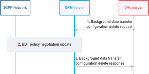
Step 1.
A VAL Server requests the NRM Server to delete its background data transfer policy configuration using the BDT_Configuration_delete_request (see clause 14.4.2.21).
The request includes identifier for the BDT policy configuration stored at the NRM server.
Step 2.
The NRM Server may perform the BDT policy negotiation update as specified in clause 4.16.7.2 of TS 23.502. If NRM server is currently serving only one VAL server, then BDT policy delete is performed as specified in clause 4.16.7.3 of TS 23.502. The request for deletion of the BDT policy configuration by the VAL server removes the requirement of the VAL server to perform BDT to the VAL UE or group of VAL UEs. This may impact the selected BDT policy.
Step 3.
The NRM Server provides a response to the VAL server indicating success or failure of the operation.
14.3.14.1 General |R19| p. 270
A service may initiate a device trigger to a UE to cause it, for example, to connect to a VAL server, to provide updated information, etc.
14.3.14.2 Device Triggering via NRM procedure |R19| p. 270
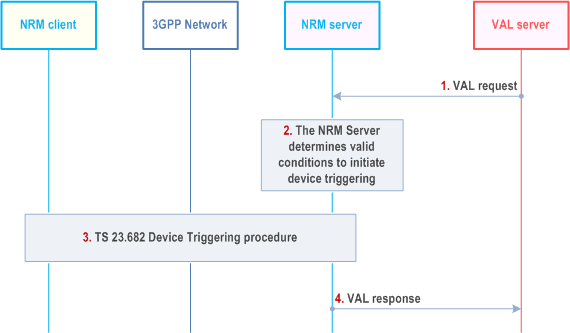
Step 1.
Based on the trigger purpose derived from the payload, the targeted NRM Client or VAL Client performs the corresponding actions (e.g., connect to the VAL Server).
The device triggering procedure is initiated by an API request from a VAL Server.
Step 2.
The NRM Server determines the valid conditions to initiate the device triggering procedure with the CN. The determination is based on request parameters as follows:
Step 3.
- If "Time Window" IE is present, the NRM Server includes its value to limit the conditions considered as valid based on step a) and/or to determine the trigger validity time value for the CN API request.
- If "Area information" IE is present, the NRM Server includes its value to limit the conditions considered as valid based on step b)
The NRM Server performs the device triggering procedure described in clause 5.2 of TS 23.682. The procedure requires that the UE Identifier, port number(s) and protocol information are available at the NRM Server. The trigger may be sent to ensure that a target UE in PSM mode is reachable when application communications resume.
As part of the procedure, the NRM Server receives a Device Triggering delivery status report from SCEF/NEF indicating the success of the delivery.
Step 4.
The NRM Server responds to the step 1 request.